Basic Understanding
In very broad terms, the ability of a vessel to maintain the true vertical can be termed as the measure of her Transverse Stability. Transverse Stability is the ability of the vessel to return to vertical when she has been heeled. The heeling could be because of an external force including the action of the sea and swell. It is always necessary to maintain stability even when a vessel has altered distribution of weights within the ship. (Loaded or discharged cargo, ballasted or deballasted her tanks, taken in or used up freshwater, fuel, stores etc). Practical stability aspects shall tell you how the ships’ officer should ensure that the ship always return to the vertical. Few basic concepts have to be recapitulated first.
Centre of gravity:
It is the Point through which a force equal to the weight of the body is considered to act vertically downwards.
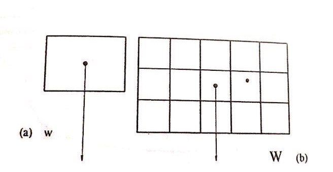
One body will have ONLY ONE centre of Gravity. In figure above, a block is shown with its centre of gravity. Its weight ‘W’ is acting vertically downwards through its Centre of Gravity.
A group of Several bodies may have their individual centres of gravity but there group as a whole is considered as one body and again will have ONLY ONE centre of Gravity. In figure ‘b’ above a group of blocks put together with their individual centres of Gravity will have only one collective centre of Gravity. The weight of the entire group ‘W’ is considered to act vertically downwards from this point, the centre of Gravity of the entire stow.
A ship acts exactly in the same manner with different centres of gravity for her cargo tanks/holds, her fuel tanks, ballast tanks etc. The ship therefore will still have only One Centre of Gravity designated by ‘G’.
Laws of flotation
When a body is put into water, it will displace water equal to its underwater Volume. If the weight of this dispLaced water is less than the weight of the body, the the body will sink e.g. a block of steel. For any floating body the weight of the displaced water must be equal to the weight of the body.
Centre Of Buoyancy
This is the point through which the force of buoyancy is considered to act vertical upwards with a force equal to the weight of the water Displaced. Centre of Buoyancy is the centre of gravity of the underwater portion.
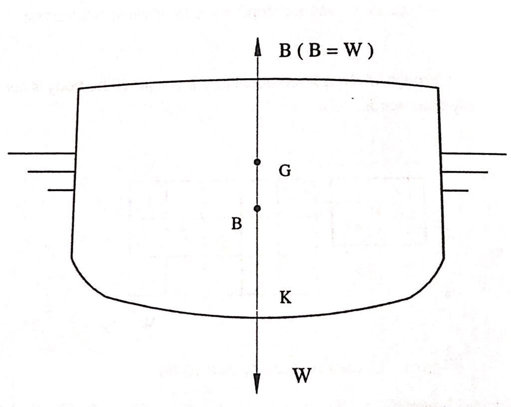
In the figure above a ship of weight W” is floating in water. Her weight is acting vertically downwards through her Centre of Gravity ‘G’. Since she is floating, the force of Buoyancy “B” must be equal to her own Weight W’ which is actually so. The force of buoyancy is acting vertically Upwards through her Centre of Buoyancy “B”.
For any body to float in a state of equilibrium in still water the Centre of Gravity (G) and Centre of Buoyancy (B) must lie in one Vertical Line. This can be confirmed from the figure above.
Laws of floatation (as adapted for ships):
- A ship must displace water that weighs exactly equal to the weight of the ship including the weights of stores, fuel, fresh water and cargoes contained within the ship.
- For a ship to float in a state of stable equilibrium in still water, the centres of Gravity & Buoyancy must lie in one vertical line.
- For a ship to float upright both the centres of Gravity and Buoyancy must lie on the vertical passing thorough the Centre line of the ship.
Note the difference between LIST and HEEL
List: when a ship in inclined out of the vertical due the unequal distribution of the weights within the ship itself, the angle of inclination is called the ‘LIST’ and the ship is said to be Listed.
Heel: when a ship is inclined out of the vertical due to external forces, like wind, sea, swell, etc.
A Listed Ship
OBSERVATION:
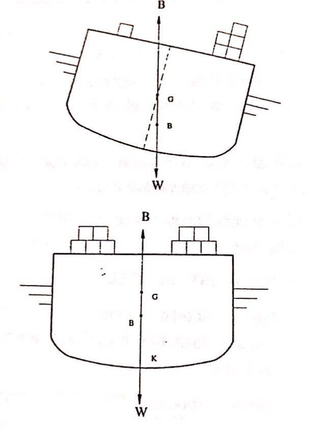
When distribution of weights within the vessel is Un-Symmetrical about the center line, the ship shall list and the points ‘B’ ‘G’ WOULD NOT lie on the vertical center line of the vessel.
Metacentre & Equilibrium
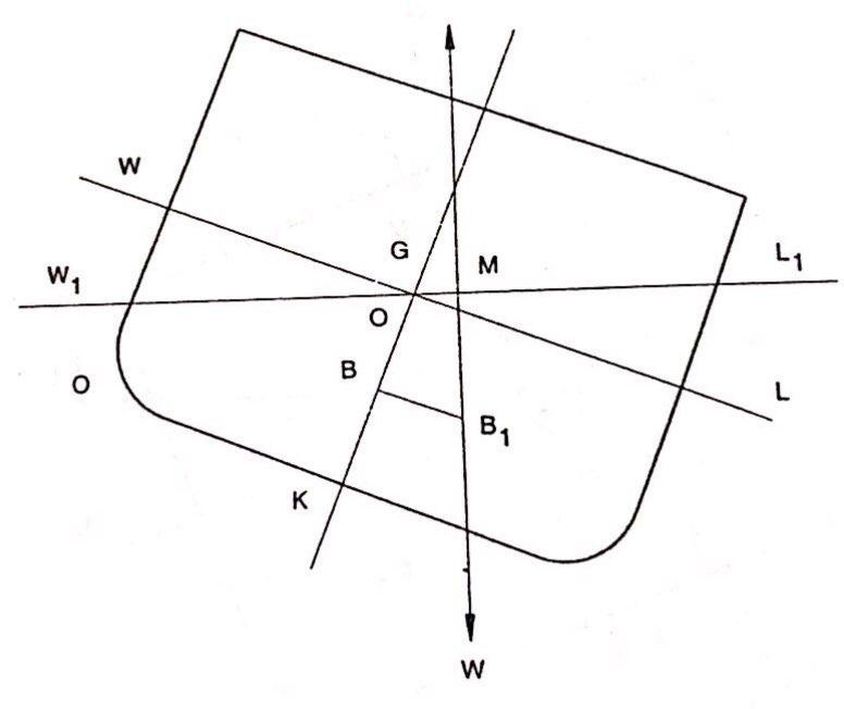
Let us now see how the situation would change when she is heeled to the one side due to external force. Since the weight on board has neither been loaded nor discharged nor shifted within the ship, the position of G can therefore be considered the same as before.
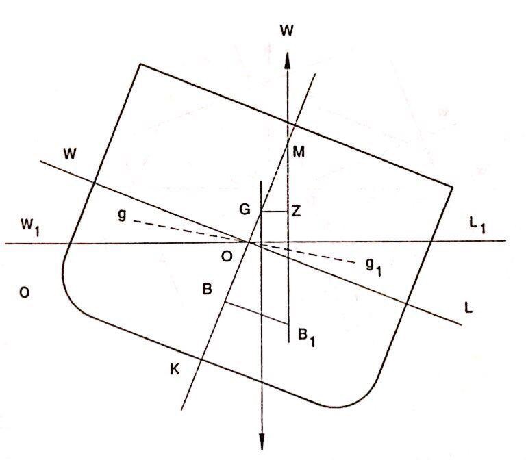
When the vessel has heeled, the shape of the underwater portion of the ship has changed. B would therefore shift out to the deeper side (remember B, the centre of buoyancy is the centre of gravity of the underwater portion). Say to B₁. This shift of B to B₁ can further be understood by considering that the wedge of water WOW₁, has been brought out of the water from the higher side and an identical wedge LOL₁ has been added to the lower side.
The Centre of gravity of the entire underwater portion of the ship therefore must move away from WOW₁, (removed portion) and move towards the added up portion LOL₁. It can be said therefore that the shift of B to B₁ is in order.
Ship Heeled Due to External force
Stable Equilibrium
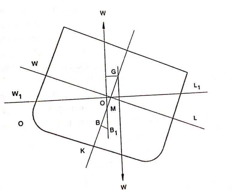
Looking carefully at the figure, we can see that force W, the weight of the ship is acting vertically downwards from G and again the same force W is acting vertically upwards through B₁. These two forces from a couple acting through the distance GZ and its tendency is to bring the ship to upright position i.e. the vessel has `Stable Equilibrium’.
Point M, called the Metacentre is the point of intersection between earlier vertical through B and the vertical through shifted centre of buoyancy, B₁. The distance GM is called the metacentric height of the ship. When M is above G, the ship is said to have positive metacentric height and the vessel has stable equilibrium.
When points G & M have merged, the ship is said to have zero metacentric height and the ship is at neutral equilibrium.
When G is above M, the ship has a Negative Metacentric Height and the vessel is in an Unstable Equilibrium.
A ship with Stable Equilibrium (having +ve GM) would oppose any heeling force and would always tend to return to upright position whenever heeled to any side. This can be confirmed from the above figure. You will notice that the righting couple is formed by two forces W (gravity) and W (buoyancy), acting opposite to each other through a distance GZ. GZ is called the Righting Lever in this case.
Neutral Equilibrium
Now studying carefully the set of figures confirm your understanding of the following facts:
Neutral Equilibrium (GM = Zero), See figure above
The ship would neither offer any resistance to heeling nor will have any tendency to return to upright position. Righting couple is zero as the Righting lever in this case is absent or GZ = Zero. The vessel therefore is at the mercy of the waves and theoretically would take any angle of heel in response to the applied external force .
Negative Equilibrium
Negative Equilibrium (Having -ve Gm).
A ship at when heeled, even very slightly would develop a lever which is acting to further heel the ship or we can say that the ship would have developed a `Capsizing Lever’.
Let us put our understanding of this module so far into a matrix so that we can refer to it quickly in future.
| Status | Position of G | Metacentric Height (GM) | Righting lever (GZ) | Righting Moment |
|---|---|---|---|---|
| Stable Equilibrium | G is located below M | GM Is positive | Ship has righting lever | Positive Moment |
| Neutral Equilibrium | G & M are coincidental | GM is ZERO | Ship has no lever | None |
| Negative Equilibrium | G is located above M | GM is Negative | Ship has Capsizing Lever | Negative Moment |
Transverse Metacentre
Figure below represents a ship inclined at a small angle from the upright by some external force. The mass is unchanged and consequently the volume of displacement (V) remains the same. it is assumed that no weights on board shift and thus CG remains unchanged. However, although the volume of displacement remains the same, the shape of this volume changes and hence CB will move from its original position. In Figure below for the upright position the waterline is WL and when inclined the waterline becomes W₁L₁.The wedge shaped volume represented by WSW₁ is termed the “emerged” wedge and the volume represented by LSL₁, which has gone into the water is termed the “immersed” wedge. The volume of the emerged wedge is equal to the volume of immersed wedge, since the ship retains the same volume of displacement. It should be noted that it is only for small angles of inclination that the point S, where WL and W₁L₁ intersect, falls on the middle line of the ship.
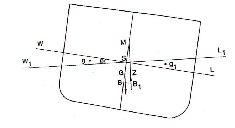
Inclination at small angles
When inclined at a small angle from the upright the new volume of displacement has its centroid at say B₁. The upward force of buoyancy must act through B₁ while the weight of the ship acts vertically downwards through G, the centre of gravity of the ship. The intersection of middle line by the vertical through B₁ at small angles of heel, at the point M is called the Transverse Metacentre. GZ is perpendicular to the vertical through B₁. There are thus equal forces acting at a distance from each other of GZ. Such a system of forces is termed a couple and in this case, the couple tends to turn the ship back to the upright.
For all practical purposes, the Metacentre is a point around which the ship inclines or oscillates.
For a ship to be in Stable equilibrium for any angle of inclination the point M must be above G the centre of gravity of the ship. it is found that for all practical purposes in normal merchant ships the point M does not change in position for inclinations up to about 15 degrees. Beyond this, it takes up different positions.
Status of stability can be determined:
In the determination of initial stability of a ship, the following criterion can be used to determine whether the ship is in stable equilibrium or unstable equilibrium or neutral equilibrium.
Ship will be in stable equilibrium If CG is below M.
Ship will be in unstable equilibrium if CG is above M.
Ship will be in neutral equilibrium if CG and M are Coincident.
The relative positions of the centre of gravity and the transverse metacentre are extremely important with regard to their effect on the ship’s initial stability. The distance GM is termed the transverse metacentric height and for angles of heel up to about 15°.
GZ = GM sin Ø.
The couple acting on the ship is:
Δ GZ or Δ GM sinØ (where Δ is the displacement)
When M is above CG there is a righting moment. GZ, the horizontal distance between the lines of action of buoyancy and weight, is known as the righting lever.
Δ GZ or Δ GM sinØ is called the moment of statical stability. This is termed the metacentric method of determining stability and is valid only for small angles up to about 15° of heel.
You should note that statical stability determines the ability of the ship to return to an upright condition while the dynamical stability determines the work done on the ship to heel her over to a given angle of heel. We shall deal with the dynamical stability in a later module.
To Determine BM
It is therefore clear that in order to determine the ships stable status we need to know the position of the centre of gravity (CG), centre of buoyancy (GB) and the Metacentre.
Calculating the moments of all weights around the keel and dividing it by the total weight shall give us CG. Centroid of the under water volume is the CB. Distance between the CB and the Metacentre (BM) however, is dependent on the moment of inertia of the waterplane area and the volume of displacement.
Assuming that the volume of displacement remains constant, and that the traverse inclination of the ship is small, i.e. < 15° then from the figure shown below:
Let v volume of immersed or emerged wedges
V = Volume of displacement of ship
GG₁ = distance between centroids of triangular wedges = 4y/3
y = half-breadth of water plane
∮L= element of length of ship
v 4/3 y = V BB₁ ————- (1)
As BB₁ = BM SinØ
Therefore, BB₁ = V BM sinØ – (for small angle sin Ø = Ø in radians)
Therefore, BB₁ = V BM Ø
Substituting for BB₁, in equation (1) we get v GG₁ = V BM Ø
Volume of the wedge of length ∮L is given by v = ∫1/2 y²Ø∮L.
= 1/2 Ø ∫ y²∮L
Substituting for v and GGi in equation (2), we get
1/2 Ø ∫ y²∮L x 4y/3 = V BM Ø
BM = (2/3 ∫ y³∮L) / V
However, 2/3 ∫ y³∮L = “I” which is transverse moment of inertia of water plane about the middle line
Therefore,
BM = I / V
Let us understand this relationship more clearly. Metacentre is the point around which the ship inclines at small angles of heel. The position of the metacentre Is determined at small angles, as the point at which the vertical passing through B meets the vertical passing downwards through G. Mathematically the BM can be determined by calculating the moment of inertia of the waterplane and the volume of displacement.
Metacentric Height.
As stated above the distance between the Transverse metacentre M and the centre of gravity G is the GM, the metacentric height. If M is above G the metacentric height is Considered as positive and if below G, it is Considered as negative.
The metacentric height ‘GM’ is the measure of initial stability of a ship at small angles of heel for all ships. In any condition of loading the GM should be positive. IMO criteria require that at all stages of loading, discharging or sailing the minimum GM should be 0.15 m.
A ship with a large GM tends to roll quickly and with a jerky motion(Stiff ship), whereas a ship with a small GM will roll slowly (tender ship) and easily and with little strain on the hull structure.
Now KM = KB + BM
However, well-calculated tables and graphs are now available in the days gone by and with smaller ships approximate expressions were used and were quite reliable.
A first Approximation to the values of KB on ship shaped vessels at load draught (H) is given by
KB = 0.52 H
A more finite value is obtained by using Morris’s Expression
Where V = displacement [m3] and A = water plane area [m2], H = Load draught.
Another very convenient expression is
KB = {Cw (Cw Cb)} H
Cb = block coefficient
Cw = water plane area coefficient
H =. Load draft