Loadlines are one of the earliest safety features introduced in shipping, At the time of introduction, ships were suffering heavy losses because of overloading. Lord Plimsoll, a member of the parliament, fought for introduction of Loadlines and hence the term “plimsoll disc”. The safety of the ship is of paramount importance and all your energy must be devoted in that direction. An overloaded ship is an unsafe ship, as it does not have adequate reserve buoyancy and strength to face the elements.
How, when and why loadline marks came into being
The origin of loadline marks dates back to 1876 when a member of the British parliament by the name of Samuel Plimsol took an active part in promoting the Merchant Shipping Act of 1876 (MSA). This act was the first legislation, which required all ships to carry loadline marks on each side of the vessel.
The Concept was to bring about shipboard safety for seafarers against the then greedy ship-owners that were interested only in maximising their profits by Constantly Overloading their ships, thereby jeopardising safety and life at sea.
The Load Line regulations of 1966 under the current Convention are in force now and deal with all details regarding the strength of the ship, sub-division, watertight closing devices and where needed weather tight closing appliances, load line marks and the assignment of freeboards.
The ship’s load line certificate is displayed on the ship and the master records the sailing draft and the freeboard in the official logbook. Heavy penalties and detention may be the result if a ship does not comply with the freeboard requirements and LL regulations.
Criteria for load line assignment
Load lines are assigned to ensure that the ship has sufficient freeboard to ride the seas in the prevailing weather conditions.
In such assignments, following conditions are taken into account:
- Adequate freeboard to provide reserve buoyancy even when the ship is rolling and pitching.
- Strength of the hull (ships are designed to submerge to a designed draft)
- The ability to shed seawater, off the decks. Ships are provided with either decks with only railing or bulwarks with freeing ports on the bulwarks. Ships also have decks with sheer, which rise in the fore and aft direction so that the water drains off. Ships also have a camber, which allows the water to drain off to the scuppers.
- Means of closing the number of openings on the main deck.
- The sub-division of the hull to ensure damage stability even when one or more compartments get flooded.
Location of deckline, the Plimsol disc and assigned freeboard.
The deckline is located amidships in line with the uppermost continuous plating (weather deck) where it meets the sheer strake (the upper most plate (strake) of the ship’s side).
In case you are on a ship with a ’rounded sheer strake, you will observe that the deck line is located lower down where the curvature of the sheer strake ends.
Various load line marks, dimensions and their location
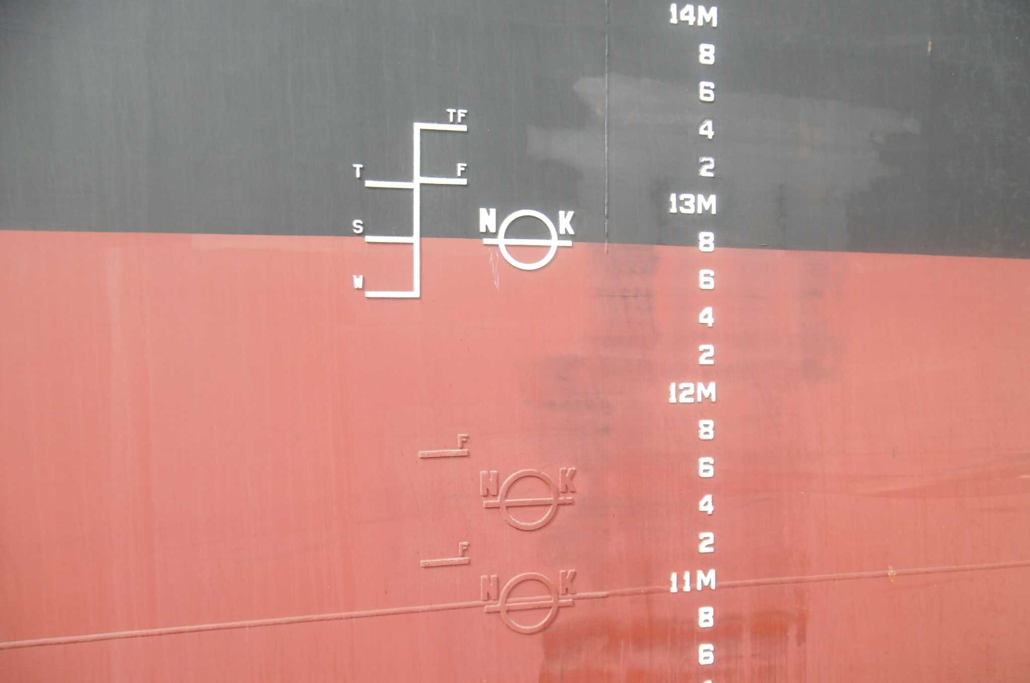
On the side of the ship on both sides amidships, are marked a set of lines as shown in the figure. These are called LOAD LINES.
- Right at the top is the deck line. It is 300 mm long and 25 mm wide with its upper edge in line with the uppermost continuous watertight deck.
- Vertically below the deck line is a circle whose outside diameter is 300 mm. It is called the loadline disc, or Plimsoll.
- A horizontal line 450-mm long and 25 mm wide cuts through the loadline disc. it is called the Plimsol line. Its upper edge passes through the centre of the disc. The letters L and R are initials of the assigning authority – in this case Lloyds Register. These letters may sometimes be IR AB, BV or the initials of any other assigning authority. IR stands for Indian Register of Shipping. The height of these letters is 115 mm and their width is 75 mm. The gap between the Plimsol line and these letters are 38 mm in height.
- A set of lines each 230 mm long and 25 mm wide marked TF, F, T, S, N, WNA are marked 540 mm forward of the centre of the loadline disc. They are on the right of the disc on the starboard side and on the left side of the disc on the port side (i.e. forward of the Plimsoll mark).
Load line zones
The oceans are divided into various zones these consist of
Summer – S
Tropical – T
Winter – W
Winter north Atlantic – WNA
Fresh water – F
Tropical fresh – TF
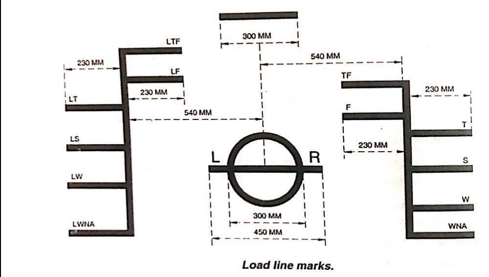
Load line marks
In the figure above, you would notice two sets of toad lines. The one on the right the normal load line and one on the right hand include marks for a ship carrying lumber or timber on its deck. (Hence the prefix “L”)
Load lines and zones
Zones are marked as areas along with the dates of its applicability on a special chart called the LOADLINE ZONE chart. You will find this chart prominently displayed on the bridge and in the cargo office. A certain area could be summer zone during certain months and tropical or winter during the remaining months (see Zone chart on board your ship). These are called seasonal zones.
It is mandatory for a ship to ensure that at all time on its voyage that the appropriate load line is not submerged neither in port nor during any stage of the voyage nor when passing from one zone to the other.
- When a ship is in tropical zone and in seawater of density 1025, she must not load to more than the upper edge of the line marked T.
- When a ship is in summer zone and in the seawater of density 1025, she must not load to more than the upper edge of the line marked S. Incidentally, this line is at the same level as the line passing through the centre of the load line disc.
- When a ship is in winter zone and in seawater of density 1025, she must not load to more than the upper edge of the line marked W. .
- In the Winter North Atlantic the seas are so rough that smaller ships may not remain safe if allowed to load even upto SW”. The upper edge of WNA line, which is 50 mm below the `W” line, is the maximum they can load in waters of 1025 density. Ships of more than 100 meters length do not have this limitation.
- When the density of the water is 1000 i.e. in fresh water and In summer zone a ship may load upto the upper edge of the line marked ” F”
- When the density is 1,000 i.e. in fresh water and in tropical zone, a ship may load upto the upper edge of the line marked “TF”.
Distances between the seasonal load lines
- The distances between the centre of the disc and the deck line is prescribed by the assigning authority and depends on several factors including the ships dimensions, structure, water tightness arrangements, type of cargo to be carried etc. The draft at the S line is the summer load draft.
- The distance between W and S, between T and S and between and TF is the same and is equal to 1/48th of Summer load draft.
- The distance between S and F is equal to the distance between T and TF and is the Fresh water Allowances (FWA) for that ship.
Assigning authority of the loading marks
The Flag State of a vessel is the authority. In many cases, they hand over the inspection and assignment to the classification societies, who assign the marks and issue the certificate to the ship on behalf of the Flag State.
Reading load line marks
- The ring, lines and letters shall be painted in white or yellow on a dark background, or in black on a light background.
- They should be permanently marked on both sides.
- The marks should be plainly visible.
- All readings are taken from the top of the relevant load tine mark.
Knowledge and use of draft marks (Also spelt as draught marks)
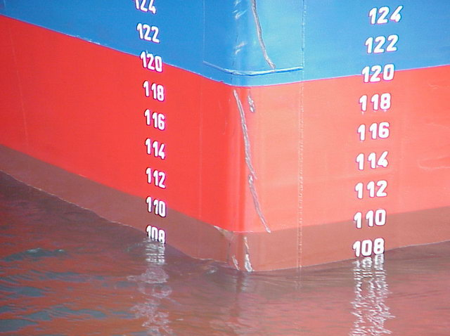
- Draft marks on a ship are located at 6 locations.
- On both sides at the bow
- On both sides amidships
- On both sides at the stern
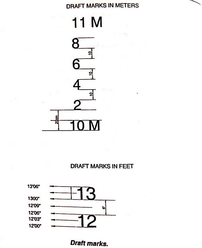
Draft marks could be either in meters or in feet or in both i.e. meters & feet.
Draft marks
Draft marks are numerals painted on the stem, amidships and stern of a ship. They indicate the depth of the ship’s keel below the water line.
The meter mark numerals are 10cms high. in between the meter marks but slightly to the right of them are marked Arabic numerals as 2, 4, 6 and 8, this indicates 20cms, 40cms and 60cms and 80cms. The’ of these Arabic numerals is 10 cm and spacing between them is 10 cm. The bottom of the numeral indicates the draft.
If the water level touches the bottom of ’10’ the draft would be 10 meters if the water level just touches the bottom of 2 then the draft level would be 10 meters and 20 cms, if the water level just touches the top of ‘2’ then the draft would be 10 meters and 30cms. if the water is at any level other than the top or the bottom mark, the draft has to be estimated. The thickness of all marks is 1 cm.
The feet are marked either in Arabic numerals or in roman. In both cases, the height of the marks is 6 inches. if the water level just touches the bottom of 12, the draft would be 12 ft. If the water level just touches the top of 12 ft, the draft would be 12 feet 6 inches. If the water level were halfway between the top of 12 and bottom of 13, the draft would be 12 ft 9 inches: The thickness of the mark is one inch.

Draft Marks