Aim
The blog shall show the process of interpreting the radar information correctly for Navigation and Collision avoidance purpose.
Introduction to the different display modes
There are two modes of displays
a The relative motion display and
b The true motion display
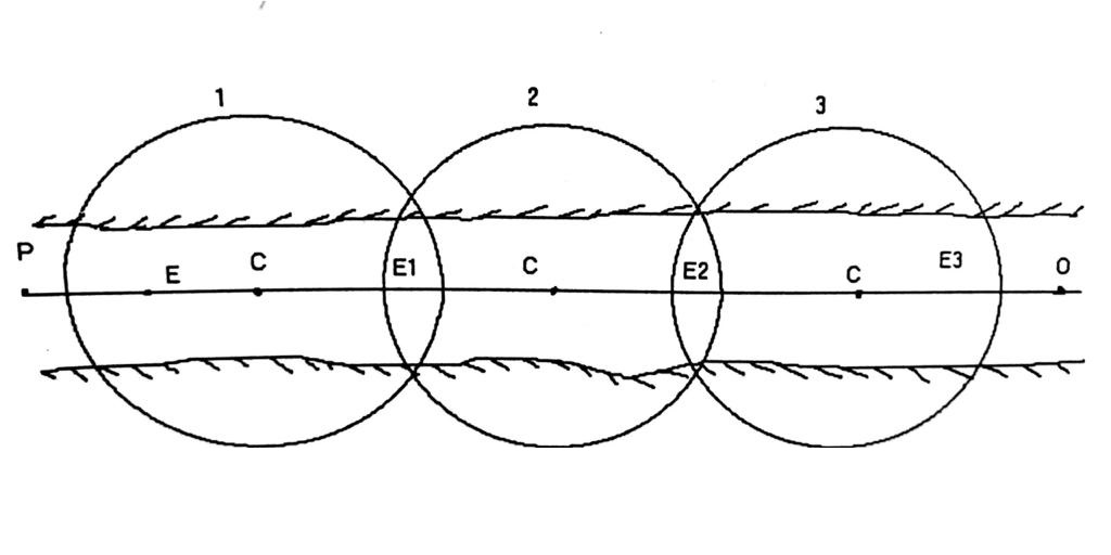
In the relative motion display the origin of the display and own vessel is assumed stationary and the movement of all the targets is show, with respect to the observing vessel (which is at the origin). The origin is located at the centre of the circular screen. The origin can be shifted from the centre so as to obtain increased range. It is then called the off centre relative motion presentation
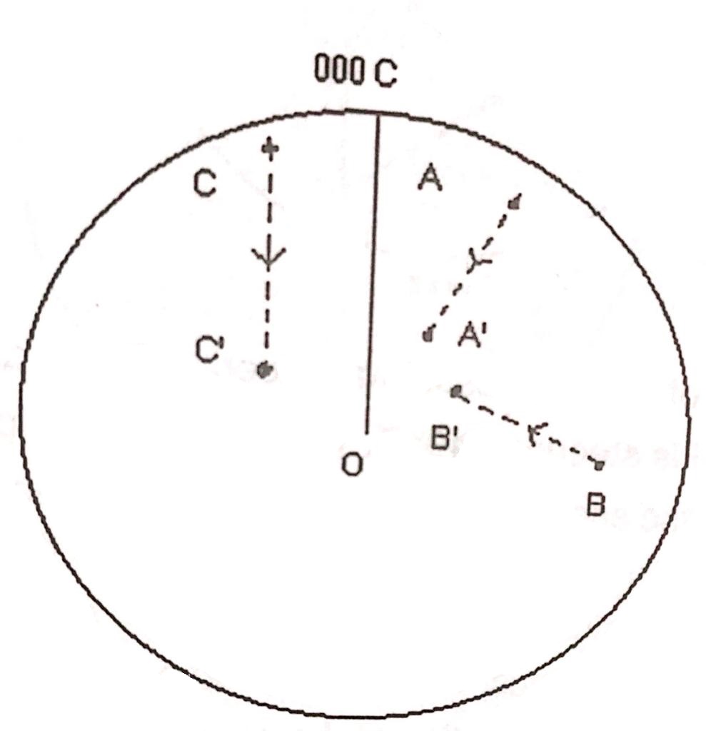
In above figure we see two ships echoes ‘A’ & ‘B’ and a stationery echo ‘C. We assume own vessel is steering 000° (T) at 12 Kt. Then in 15 minutes own vessel will move 3 miles north through the water. So the stationary echo will move down by 3 miles exactly, in the opposite i.e. in a southerly direction. If there is current it will have the same effect on all moving targets. Now consider ships A and B. In 15 min. they will move on the radar screen to A¹ and B¹ which is relative approach of the ship A & B and not the true course or speed of the ships. Hence we use the process of stationery objects as in the case of ‘C’ for ” navigation purpose” and the process of relative approach of ships A or ship B for “collision avoidance”. As is evident by producing the line joining AA¹ & BB¹ we come to know how close these ships will pass to own ship, i.e. closest point of Approach (C.P.A) and time of closest point of Approach (T.C.P.A).
In relative motion there are three modes of presentation of the display.
1. Ship’s Head up (Unstabilised)
2. North up (stabilised)
3. Course up (stabilised)
In ship’s head-up (Unstabilised) display the observer views the picture with the heading marker or the ship’s head at the ‘top’ of the screen as in the diagram.
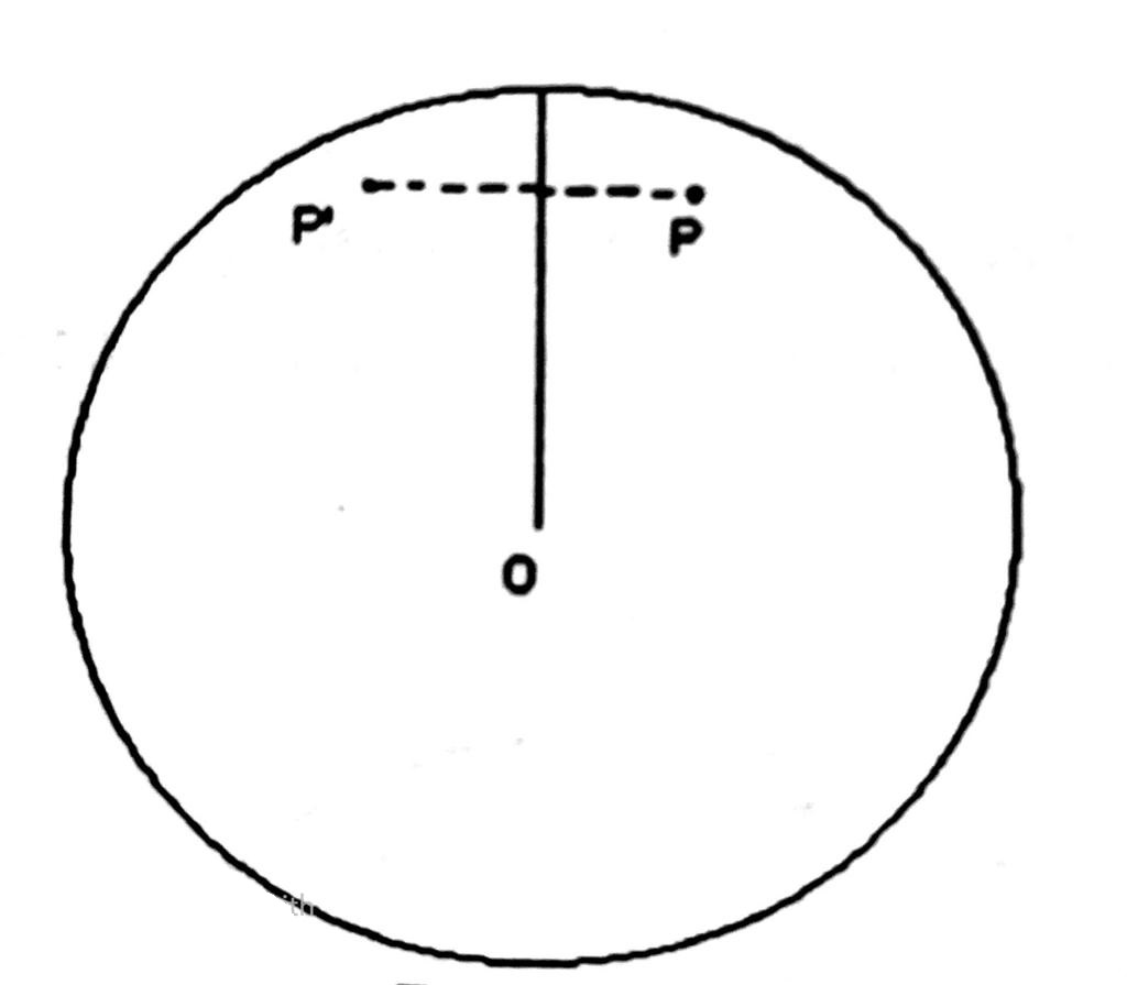
Ships Head Up Unstabilised Display
Before alteration of course, vessel was steering 210°T and after alteration of course the vessel is steering 240° T. The main advantage of this type of display is that it resembles the scene as viewed through the wheelhouse windows. Thus if you look on the radar screen or look forward through the wheelhouse window, objects on starboard side of the ship will be on the right and those on the port side will be on the port side. Thus, when on a course of 210°, if there was a target P on the starboard side, after alteration of the course the target would appear at P’ on the screen and on the port side of the heading marker
The disadvantage of un-stabilised display is that if there is a change in the direction of the observing vessel’s heading, the entire picture (besides the heading marker) will rotate by an equal amount but in the opposite direction. The land echoes get smeared across the screen during this period and obscure the small fixed targets or floating objects for some time till the vessel is steady on the new course. The bearings taken on the fixed scale are relative bearings.
In North-up stabilised display, the heading marker is aligned with the fixed scale 000° which indicates the true north (i.e. the outer azimuth 000° is aligned with fixed scale 000°) outer azimuth ring is stabilised to maintain the true north display. When the observing vessel alters course or yaws the compass stabilisation signal is used to produce simultaneously a rotation of picture in the same direction as the change of heading. As a result there is no rotation of picture on the screen. Only heading marker rotates to the new heading. The true north remains coincident with 000°on the fixed scale. The azimuth-stabilising signal is invariably from a gyrocompass.
The north-up stabilised display overcomes the disadvantages of head-up by removing the angular smearing of picture associated with any change in heading. It also allows reading off true bearings directly and quickly from the fixed bearing scale. This feature is of importance in Navigation as well as for collision avoidance.
As there is no angular disruption of the tracks of targets and as their echoes move on the screen; the systematic observation of targets for collision avoidance is greatly facilitated in the stabilised North-up display.
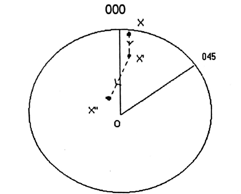
North Up Stabilised Display
In the above figure, before the alteration vessel was steering 000° (T), and after alteration vessel was steering 045° (T). Hence the echo which was moving along from X to X’ before alteration, move along X’X” after alteration.
In North-up stabilised display the picture as seen on the radar screen compares directly with chart hence is greatly used for coastal navigation position fixing.
The main disadvantage of this type of display is that while approaching a port if the observer views the radar screen & looks outside the wheel house window, he finds it difficult to compare the radar picture with the visual view, particularly while on a southerly course. Because visually he sees the land ahead where as on the radar P.P.I the heading marker is on 180° which is astern & the land echoes also seen to be astern (this is awkward)
In a course-up (stabilised) display the heading marker is aligned to 000° on the fixed scale at an instant at which vessel is right on the course. Due to azimuth stabilisation, changes in the vessels course doesn’t change the heading marker & maintains the ship’s course aligned to the zero of the fixed bearing scale.
The angular wander of echoes associated is also eliminated. This type of display combines the feature of both previous displays (Head up-un-stabilised and North-up stabilised)) It eliminates the angular wander of the picture due to yaw while maintaining the heading marker in the ship’s head up position.
In some radar sets a large alternation of course may require the observer to realign the heading marker to the zero of the fixed scale by pressing a button and following the process of realignment.
In the course-up (stabilised display), the bearings are true bearings, if read-off on the outer azimuth ring and relative bearing, if read-off on the inner fixed bearing scale.
For navigation & collision avoidance, course-up (stabilised) display is preferred. Only in specialised pilotage areas ship’s head-up display mode is used.
In True motion display, the echo movement of all targets is shown independent of the motion of the observing vessel. This is achieved by causing the origin of the picture to track across the screen in a direction and at the rate of motion of the observing vessel. Then the question arises that whether we should measure the observing vessel’s course and speed with respect to the sea or with respect to land, i.e. what is made good.
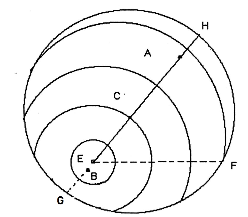
C: Centre of PPI
E: Present position of origin
EH: Heading Marker
CA=CB=about 75% of radius of PPI
A: Limiting point of this run
B: Jump back point of this run
EF: Electronic bearing line Circles around E are range rings
The principle of true motion is better illustrated with the help of following figure
If the course & speed is measured with respect to what the observing vessel is making through the water the true motion display is called sea-stabilised. In which case the course & speed of own vessel is fed & a stabilised picture is obtained.
If the course & speed is measured with respect to what the own ship is making good over the ground taking into account the effect of current then the true motion display is called ground-stabilised. In which case along with observing vessel’s course & speed the direction of current & the rate of current is also fed & a stabilised picture is obtained.
Hence in a true motion sea-stabilised display the stationary targets will move in the direction of the current at the rate of the current.
Whereas in a true motion ground stabilised display the stationery targets will be stationery as the effect of current is already taken into account by feeding the data along with own ship course & speed.
Collision Avoidance
Introduction.
In order to use radar information for collision avoidance we have to monitor the movement of the echoes i.e. the rate of change of its range & bearing. Radar is capable of displaying the immediate range and bearing of an echo. To interpret that information for collision avoidance you will have to do the plotting of the history of the echo movement manually on paper, or by the reflection plotter or by using the plotting aids provided (ARPA).
To come to any conclusion two levels of information is required.
- When the risk of collision is indicated by the relative track we have to determine the action to be taken and,
- Determine the true motion of the target to decide the choice of action to be taken.
All of this information may be displayed on the radar and the relative motion is tracked by simply recording the Positions of the echo at equal time intervals. Using the basic Plotting triangle or OAW triangle allows us to obtain additional information & to analyse the movement of the echo.
In the diagram you see, the relative motion of the target has been tracked by several plots taken at equal intervals of time (say at 12-min interval).
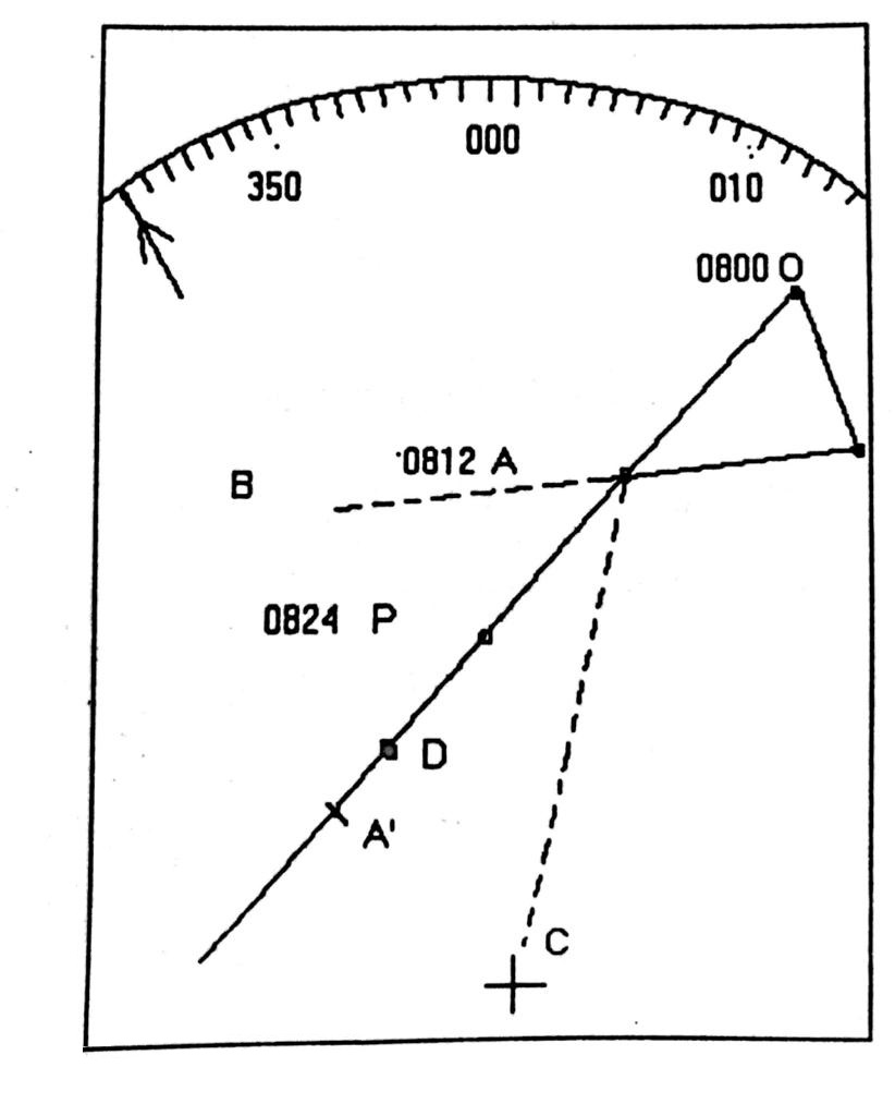
C : Position of own ship
OA : Target’s apparent motion
WO : Own ship’s course and speed
WA : Target’s true course and speed
OA’ : Predicted apparent path of the target if neither vessel alters course or speed.
CA’ : Closest point of approach (CPA)
OA’ I OA : Time to CPA (TCPA)
∠BAC : Aspect or angle between target ships heading and the bearing of own ship from target ship
CD : Distance the target will pass ahead of own ship
OW : The target if stationary will move along this line.
First bearing at 0800 hrs 015° (T) X 10′.
Second bearing 0812 hrs 007°(T) X 08′ &
third bearing at 0824 hrs 358° X 06′
To draw the OAW triangle plot the three bearings & distances. First bearing & distance is ‘O’ & the second bearing and distance is ‘A’. Join OA & extends to A’.
Draw own ship’s course in reverse direction from and cut out own ship’s speed for 12 min which is W.
Join WO & WA Then:
C-Position of own ship
OA- Apparent path of target.
OW- Own ships course and speed reversed
True motion information is found during the plotting interval. When the relative track is plotted, the vector resolved shows the course of the target relative to own course and the proportional speed. Exact speed can be found by simple calculations,
If the closest point of approach (CPA) is zero, the target is on collision course. From the OAW triangle, you can find the time at which collision will occur by calculating on the targets apparent motion track.
In Case of risk of collision exist either the target vessel or own ship has to take avoiding action as per rules (Collision Regulations)
thank you ,it was really helpfull