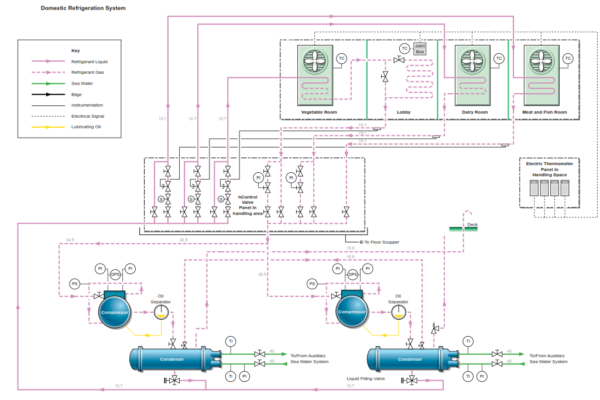
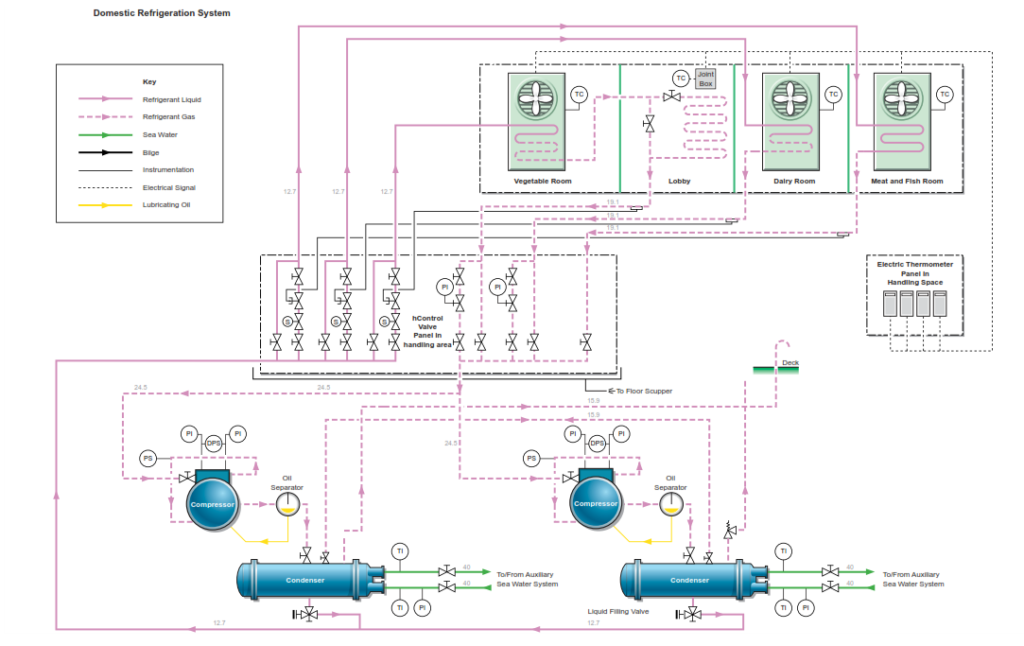
Cooling for the meat/fish, vegetable and dairy rooms is provided by a direct expansion R-404a refrigeration system. The plant is automatic and consists of two compressors, two condensers and an evaporator coil in each of the three cold and cool rooms; the lobby is cooled by the refrigerant return coil from the vegetable room. During operation, one compressor will control all the rooms while the other serves as standby, but on manual start up mode with all its valves closed until required
Note: To comply with the Montreal Protocol, the maximum annual leakage of this gas into the atmosphere should be restricted to 10% of the total system charge. To verify this and to monitor the number of times the system has to be recharged, a record has to be made in the refrigerant recharge log. A regular system of leak detection to minimize gas leaks is to be implemented to ensure leaks are detected at an early stage
Air in the cold and cool rooms is circulated over the evaporator coils by electrically driven fans. The room evaporators are equipped with timer controlled electric defrosting elements. The frequency of defrosting is chosen by means of a defrosting relay built into the starter panel. This is normally set for 20-30 minutes every 12 hours.
In the lobby there is a steel coil where the gas returning from the vegetable room imparts a small cooling effect, but also warms the refrigerant gas returning to the compressor. The compressor draws R-404a cold refrigerant vapor from the cold and cool room evaporators and pumps it under pressure to the sea water cooled condenser where the hot gas is condensed into cool liquid refrigerant. The liquid refrigerant is directed to the distribution manifold for the refrigerated room evaporator units.
CAUTION: The system is not fitted wilt a liquid line filter dryer or liquid line sight glass so extreme caution should be taken when adding refrigerant to the system. If possible a temporary dryer should be fitted inth the top up system as any trace of moisture in the refrigerant system will lead to problems with the thermostatic expansion valves icing up and subsequently blocking.
The compressors are protected by high pressure and low pressure cut-out switches.
A thermostat in each room enables a temperature regulating device to operate the solenoid valves independently, so as to reduce the number of starts and the running time of the compressor. The evaporators accept the refrigerant as it expands into a super-cooled vapor, under the control of the expansion valves. This vapor is then returned to the compressor through the non-return valves.
When all the solenoid valves on the evaporators are closed by the room thermostats, the low pressure switches at the compressor inlet will stop the compressors running.
Any leaks of refrigerant gas from the system will result in the system becoming undercharged. The symptoms of this will be low compressor suction and discharge pressures with the system eventually becoming ineffective. Bubbles will also become visible in the sight glass downstream of the condenser.
A side effect of low refrigerant gas charge is apparent low lubricating oil level in the compressor sump. A low charge level will result in excess oil being entrapped in the circulating refrigerant, thus the level in the sump will drop. When the system is charged to full capacity the excess oil will be separated out and returned to the sump. If the system does become undercharged the whole system should be checked for leakage.
When required, additional refrigerant can be added through the charging valve, after first venting the connection between the refrigerant bottle and the charging connection.
CAUTION: Refrigerant R404a is a gas mixture. If gas is lost it may be one component of the mixture and a top up with new refrigerant may result in a slight change in the composition. If a substantial leak has occurred, in order to guarantee correct composition, the system should be evacuated and charged with a fresh refrigerant charge.
Operating Procedures
To Start the Refrigeration Plant
a) All system valves, except the compressor suction valve should be opened and fully back seated to prevent gas leakage through the valve gland. Check that the correct cut-in and cut-out values are set according to the system design book.
b) Check that the oil level within the sump is correct.
c) Check the settings for the automatic cut-outs on the compressor.
d) Open the valves for the sea water cooling supply and return valves for the refrigeration units and check there is sufficient flow through the condensers.
e) Open the refrigerant supply and return valves on the evaporators in each refrigerated room.
f) Start up the auxiliary sea water cooling system if not already operating.
g) Open the compressor suction valve half way and start the compressor; check the rotational direction is correct if the compressor drive motor has been overhauled or replaced.
CAUTION:If there is any knocking noise from the compressor during start-up it indicates that there is liquid refrigerant returning to the compressor. If knocking is heard stop the compressor immediately and repeat the start- up procedure. If necessary run the compressor for a few seconds at a time, with a 30 to 40 second gap between starts.
h) If the compressor is operating satisfactorily leave it running.
i) Continue opening the suction valve slowly taking care not to allow liquid into the compressor.
j) Allow the compressor to settle to normal operation.
k) Check that the oil return pipe from the oil separator is warm, indicating that the separated lubricating oil is returning the compressor sump.
Whilst running
- Check the refrigerant pressure and temperature readings
- Check the oil level and oil pressure
- Check for leakages
Shutting Down the Refrigeration Plant
This description assumes that the refrigeration plant is being shut down for a prolonged period. If the refrigeration plant is just being stopped for a short period of time the electrical power supply to the compressor motor is shut off, the cooling water flow is stopped and the refrigerant gas valve to the evaporators is closed.
a) Shut off the liquid outlet valve from the receiver and pump down the refrigerant in the evaporators to the condenser.
b) Allow the temperature in the evaporators to rise, then repeat the evacuation process.
c) When the suction pressure is slightly above atmospheric, stop the compressor. Shut the suction and discharge valves and shut the oil return valve.
d) Shut off the cooling water supply to the condenser.
e) Shut the gas inlet valve to the condenser so trapping all of the refrigerant in the condenser and receiver.
f) Isolate the electrical supply.
Defrosting
The evaporators in the meat/fish room is fitted with an electrical defrosting system. The evaporator and drip trays in the room are provided with electric heating elements. The frequency of defrosting is chosen by means of a defrosting relay built into the starter panel.
The defrosting procedure is as follows:
a) All of the solenoid valves in the system close and the compressor stops. The evaporator fans stop.
b) The electric heating element in the meat/fish room is switched on.
c) With the cooler covered in ice, the melting takes nearly all of the heat supplied and the temperature of the cooler and refrigerant is kept near zero. When the ice has melted, the refrigerant temperature rises in the room.
d) When the temperature reaches the predetermined set point on the defrosting thermostat of approximately +10°C, or when the maximum permissible defrost time has elapsed, the heating elements are switched off.
e) The compressor will restart.
f) When the coil surface temperature in the meat/fish room has gone below freezing point, the fan in that room will restart.
g) The system is now back on the refrigeration cycle and all of the solenoid valves operate again to regulate the temperatures in the spaces.
Because the operating temperatures of both the dairy and vegetable rooms remain at +3°C, the evaporators do not require defrosting and so no heaters are operated.
System Running Checks at Regular Intervals
- Lubricating oil levels in the crankcase
- Lubricating oil pressure
- Moisture indicators
- Suction and discharge pressure and temperature and any unusual variations investigated
- Check all room temperatures and evaporation coils for any sign of frosting
Shutting Down the Refrigeration Plant for Maintenance
If the plant is to be shut down for maintenance or repair and it involves opening up the compressors or breaking into the refrigerant lines, the refrigerant must first be pumped down to the condenser and locked in a similar way to that described in the section for routine plant shutdown. However pumping down until the LP cut-out trips the machine will usually not capture all the refrigerant, which may be entrained in the lubrication oil in the compressor sump and around the system. To ensure that the entire refrigerant charge is pumped into the condenser the system is run until the LP cutout trips compressor and the condenser is isolated. The low pressure in the system will allow any refrigerant to evaporate and the process of pumping down until the LP cutout trips the compressor again. This process is repeated at hourly intervals until there is no rise in system pressure following LP cutout.
When complete, the inlet and outlet valves must be kept closed until all maintenance work has been completed and the system returned to normal operation.
If more substantial repairs are to be undertaken, it may be necessary to remove all of the refrigerant from the system. Because this operation involves evacuating the condenser and pressurizing cylinders, it should only be undertaken by a member of ship’s staff trained in this operation or by a qualified service engineer. Additionally, for safety reasons, reference should be made to the maker’s operating manuals before undertaking this task.
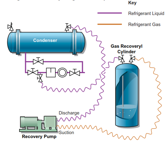
The first stage in this process is to shut down the refrigeration plant in accordance with the previously described procedure. For full refrigerant evacuation, a designated gas recovery unit must be used together with dedicated gas recovery cylinders. The cylinders used to charge the system cannot be used as they will typically only have a single non-return valve on the top of the bottle as opposed to a normal recovery bottle that has two isolating valves, one for gas and one for liquid, and an internal dropper pipe from the liquid valve.
The liquid valve from the recovery cylinder must first be connected via a flexible hose and isolating valve to the bottom of the condenser and the gas valve of the cylinder connected in a similar manner to the suction side of the recovery pump. The discharge side of the recovery pump must then be connected to the top/gas side of the condenser. With the valves open to the bottle and recovery pump, the pump is to be run until all of the liquid refrigerant has been evacuated. The purpose of the pump is to compress gas evaporating from the top of the recovery bottle and use it to put a positive pressure inside the condenser on top of the liquid refrigerant.
Refrigerant Recovery Stage One – Liquid
When all liquid has been expelled, the connections to the recovery pump need to be changed. The suction side of the pump now needs to be connected to the condenser. The pump’s discharge should be connected to the liquid connection on the recovery bottle and the gas valve on the recovery bottle either left closed or also connected to the inlet side of the recovery pump. Using this method all of the gas is then removed from the condenser. The gaseous refrigerant passes through the recovery pump where it is condensed in its own air cooled condenser and pumped into the liquid connection on the recovery bottle.
Refrigerant Recovery Stage Two – Gas
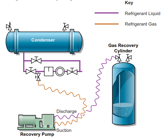
When the unit has been run sufficiently and allowed to pull a small vacuum on the main condenser, all of the refrigerant gas will have been removed. Switching off the pump and closing all of the valves will allow any necessary maintenance work to be undertaken. During this operation a set of weighing scales must be used to ensure the recovery bottles are not overfilled. It is important to ensure that any bottle used is only filled to 80% capacity. The scales will also allow a record of the amount of gas recovered to be logged in the refrigerant log book.
Charging the Refrigeration Plant Following Maintenance
Note: The ship may not be carrying sufficient nitrogen for this process to be carried out, but it is the recommended practice.
Before reintroducing any refrigerant into the system, all repair works must have been completed and the pipelines and compressors visually checked for integrity. A vacuum pump, not the recovery pump, must then be used to create a vacuum in the system. A vacuum of 10 torr will be sufficient. This will allow leakage checks to be undertaken and also ensure any atmospheric moisture has been removed before refrigerant is introduced.
Note: If there is water in liquid form in the system, rapid evacuation may cause the water to freeze. If this happens there will be a rise in pressure (loss of vacuum) which could be confused with a pipework leak.
The vacuum is broken by flooding the system with nitrogen and again a pressure test, this time with positive pressure is carried out. The nitrogen pressure is released to atmosphere until there is a slight positive pressure in the system and the vacuum pump then used to re-evacuate the system. The vacuum is held for sufficient time to confirm no leakage.
The system is now ready to introduce refrigerant via a flexible hose into the condenser. The exact charge will be noted in the manufacturer’s handbook and is checked by suspending the refrigerant bottle from a set of scales. With modern refrigerants being gas mixtures, charging is always done via the liquid line as this ensures correct composition. If the bottle only has one valve, the bottle must be inverted prior to charging.