The air conditioning system is designed to cool air if required, provide heating to the air when needed and humidify the air to the correct level for comfort. A by product of air conditioning is the lowering of the air’s dew point and precipitation of moisture out of the air and making it dryer.
A comfortable atmosphere is a combination of temperature and humidity and both must be controlled. The level of humidity is important for comfort so it is necessary to humidify the air again by spraying steam into the circulating air flow.
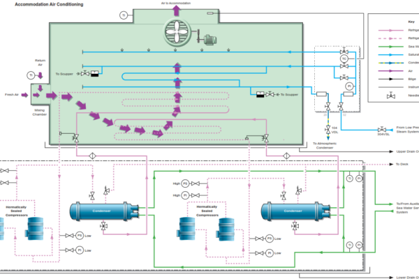
The air conditioning plant is a package type unit which contains all items required for providing cooled or heated air to the accommodation spaces. The cooling of air is obtained by a refrigeration system which is operated by four hermetically sealed compressors; the compressors are in two groups of two. Heating is by means of a steam coil and humidification is supplied by means of steam injection into the air flow to the accommodation spaces.
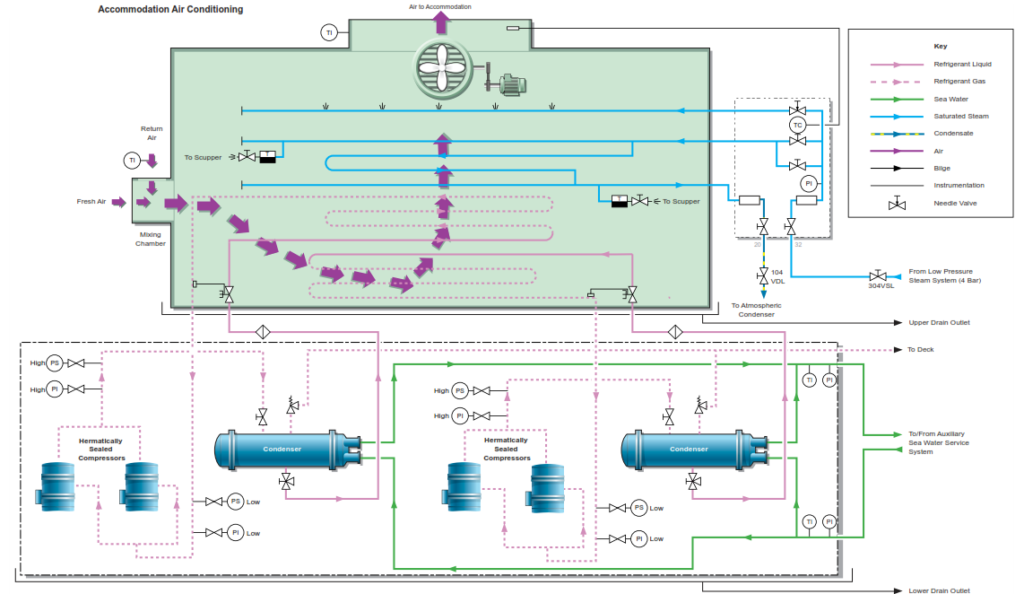
Air is supplied to the accommodation by the single air conditioning unit located on the upper deck cross alleyway. A belt driven fan draws air through the body of the air conditioning unit which has the following parts:
- Mixing chamber for fresh and recirculated air
- Filter
- Heating coil (steam)
- Air cooler
- Steam humidifier nozzles
- Water eliminator section (drain)
WARNING:- It is essential that no water should be lying in the air conditioning system as at the right temperatures, this can become a breeding ground for legionella bacteria which can have serious, or even fatal, consequences. The drain should be kept clear and areas where water can lie should be sterilised at frequent intervals.
Air is forced into the distribution trunking which supplies the accommodation block. It may be drawn into the system either from outside or from the accommodation via recirculation trunking. The ratio of recirculated to fresh air can be manually adjusted at the inlet to the air conditioning unit. During winter and summer months a 30% fresh air ratio is used and at intermediate seasons 50% fresh air ratio is used.
The inlet filters are of the washable mat type and they should be cleaned at regular intervals before the air flow is restricted; the frequency of cleaning should be increased when operating in dusty conditions. Heating is provided by a finned heat exchanger supplied by steam from the .88MPa system.
Cooling is provided by a direct expansion R-404a system. The plant is automatic and consists of two compressor/condenser units each supplying a separate evaporator contained within the air handling section of the air conditioning unit. The evaporators consist of finned copper tubes through which the expanding refrigerant gas flows and over which the air flows.
A single compressor/condensing/evaporator unit may be able to meet the cooling requirements under certain conditions, however, if the cooling demand increases the second compressor /condensing /evaporator unit will automatically start in order to meet the demand. Each compressor /condensing /evaporator unit has two identical compressors and normally only one compressor will operate in each compressor/condensing/evaporator unit.
The compressor takes suction from the returning superheated gas from the evaporator inside the air handling section. After compressing and raising the pressure of the gas to in the region of 20MPa, it leaves as a superheated gas which is then passed to the condenser where it is cooled by the auxiliary sea water cooling system into the liquid refrigerant state.
The liquid R-404a then flows, via a filter dryer unit, back to the expansion valves of the evaporator inside the air handling section. The expansion valve is regulated by the operating parameters selected at the control panel by the duty engineer. Once expanded through the evaporator and converted back to a superheated gas, it then returns back to the compressor to repeat the cycle.
The refrigerant expansion valve is designed to regulate the superheat of the refrigerant gas in the evaporator. During cooling down after the plant has been started, the valve regulates the flow through the evaporator based on the lowest allowable superheat temperature in the compressor suction lines. When the temperature has been sufficiently reduced, the valve regulates according to the supply air temperature.
The compressors are protected by high and low gas pressure cut-out switches, and overcurrent relays. The shutdowns must be reset manually before the equipment can be run.
Hermetically sealed compressor systems are less prone to leakage and are fitted with less instrumentation, so monitoring gas pressures to determine the charge is not possible, however a reduction in the temperature on the compressor discharge could be indicating loss of charge and a leak test should be undertaken.
Note: To comply with the Montreal Protocol, the maximum annual leakage of this gas into the atmosphere should be restricted to 10% of the total system charge. To verify this and to monitor the number of times the system has to be recharged, a record has to be made in the refrigerant recharge log. A regular system of leak detection to minimize gas leaks is to be implemented to ensure leaks are detected at an early stage.
CAUTION: Refrigerant R404a is a gas mixture. If gas is lost it may be one component of the mixture and a top up with new refrigerant may result in a slight change in the composition. If a substantial leak has occurred, in order to guarantee correct composition, the system should be evacuated and charged with a fresh refrigerant charge.
If required, additional liquid refrigerant can be added through the charging line, after first venting the connection between the refrigerant bottle and the charging connection. Care must be taken to ensure that no moisture or dirt is drawn into the system as any trace of moisture in the refrigerant may lead to problems with icing of the thermostatic expansion valve and subsequent blockage.
CAUTION:Because of the limited instrumentation, only very small amounts of refrigeration should be added at any one time.
Inspection Before Operating the Air Conditioning System
- Check refrigerant pipe joints and the electrical system for loose connections and damaged wires
- Check the condenser water supply and pressure, vent air from the top of the condensers, check the condensers for water leakage and check the refrigerant level in the condenser to ensure a full charge
- Check the fan drive belt tension (about 10mm total at the mid length) and condition
- Check that the fan drive belts are parallel and that the drive moves smoothly by hand
Operation of the Air Conditioning System
The air conditioning system is designed to run with one compressor operating on each of the two evaporator sections. Inside the air conditioning unit there are two evaporators or cooling sections. These are identical to each other but are controlled by separate expansion valves and are fed internally by different compressor systems.
Steam is supplied via spray nozzles in order to control the humidity of the air being supplied to the accommodation spaces.
The control panel on the air conditioning unit has two main switches (breakers), one for the air fan unit and one for the compressors. When the fan main switch is turned to the ON position the air fan and its related parts are electrically energized. When the compressor switch is turned to the ON position the compressors and their crankcase heaters are energized.
The fan is started by pressing the FAN pushbutton at the master controller. The master controller has two other pushbuttons, an OFF pushbutton, for stopping the air conditioning unit, and a COOL/HEAT pushbutton which starts the compressor when cooling is required or activates the heater when heating is required. Heating or cooling is selected by means of the COOL/HEAT selector switch.
For each pair of compressors there is a sequence start switch which enables No.1 or No.2 compressor in the pair to be selected as the first start compressor.
Indicator lamps are provided for ‘Power’, ‘Operation’ and ‘Alarm’.
Procedure for Starting the Air Conditioning Fan
The recirculation air damper is set to the desired amount of recirculated air/ fresh air. The steam supply and condensate drain valves to the air conditioning unit must be open. Steam supplies heating when required and also maintains the desired air humidity (steam supply valve must be open together with the local steam valves at the unit). Drains from the air chamber must always be clear and during operation of the air conditioning unit the duty engineer must ensure that condensed water vapor is draining from these drain lines.
a) Supply electrical power to the air conditioning unit and select LOCAL at the REMOTE/LOCAL changeover switch.
b) Operate the switch (breaker) for the fan; the fan power lamp will illuminate.
c) Press the FAN pushbutton on the master controller. The fan will start and the operation lamp will illuminate.
d) Check the fan operational direction is correct, that there is no abnormal noise and that the electric motor current is within acceptable limits (15 – 17A).
Operation of the Air Conditioning Cooling System
The cooling system is started when the fan is running correctly. It is assumed that items a) to d) above have been completed successfully.
e) Select COOL at the COOL/HEAT selector switch.
f) Operate the switch (breaker) for the compressor.
g) Press the COOL/HEAT pushbutton on the master controller. The cooling system will start; the selected first start compressor will operate.
h) The temperature may be regulated by means of the thermostat.
The cooling system will operate automatically to maintain the desired temperature and humidity. The unit designed conditions are 27oC and 50% relative humidity.
Operation of the Air Conditioning Heating System
The heating system is started when the fan is running correctly. It is assumed that items a) to d) above have been completed successfully.
e) Select HEAT at the COOL/HEAT selector switch.
f) Fully close the needle valve for steam spray and open the steam inlet valve to the steam valve panel. Open the steam spray valve by 0.25 turn.
g) Regulate the desired temperature by means of the temperature regulator
h) Press the COOL/HEAT pushbutton on the master controller in order to activate the heating system.
Stopping the Systems
The heating system is stopped by pressing the COOL/HEAT pushbutton whilst the heating system is running and then closing the steam supply valve to the steam inlet panel; the other steam valves must also be closed. The cooling system is stopped by pressing the COOL/HEAT pushbutton whilst the cooling system is operating and then by opening the switch (breaker) for the compressor so that the compressor stops.
The fan is stopped by pressing the FAN pushbutton when the fan is running and then opening the switch (breaker) for the fan; the fan will stop and the operation lamp will be extinguished.
To Shut Down the Compressor for a Prolonged Period
Leaving the system with full refrigerant pressure in the lines increases the possibility of losing charge through system leaks or through the compressor’s drive end shaft seal. If the air conditioning system is to be shut down for a prolonged period, it is advisable to pump down the system and isolate the refrigerant gas charge in the condenser.
Shutting Down the Refrigeration Plant for Maintenance
Hermetically sealed compressor systems would normally be maintained by specialist contractors, however it would still be advisable to pump down the refrigerant into the condenser prior to tie maintenance team’s arrival.