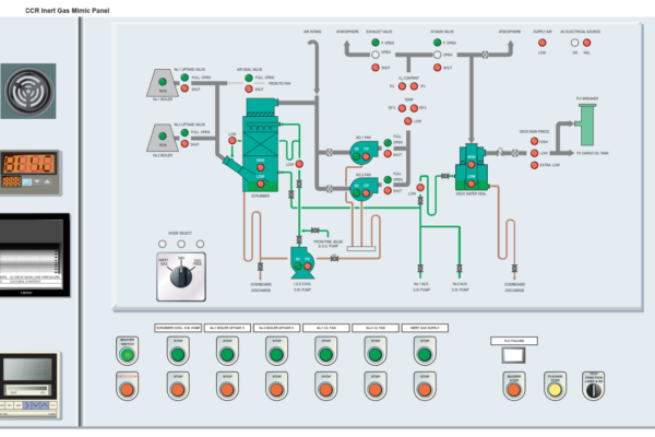
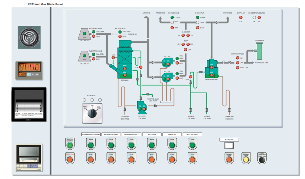
The flue gas system main control panel is situated in the CCR. This panel contains the programmable controller pushbuttons etc, which takes care of the start/stop/alarm functions and the running mode. On the front of the panel the system is represented in the form of a mimic diagram, with appropriate indications and pushbuttons. The panel also contains an indicator unit for IG main pressure on the deck lines and the IG O2% content.
A sub-panel on the bridge contains indication for inert gas pressure, oxygen content and alarm indicators.
Procedure for Operating the Inert Gas System
Starting
a) The deck seal is constantly supplied with sea water by one of the auxiliary sea water supply pumps. In normal operation one pump is constantly running in manual mode, with the other pump on standby back-up mode.
The engine room department will commission the oxygen analyser at least 15 minutes before the IG plant is required and steam blow the boiler uptake valves from the boilers.
On the IG control panel in the CCR set the system selector switch to INERT GAS then push MASTER SWITCH and confirm the lighting of the indicator lamp.
b) Ensure the engine room department has manually opened the scrubber sea water supply pump suction, discharge and the scrubber overboard discharge valve in the engine room. When confirmed ready, press the IGS SCRUBBER PUMP start button on the control panel and confirm the RUN indication lamp is lit. If the scrubber pump is unavailable, either of the fire and bilge or fire and GS pumps can be utilised to supply the scrubber tower.
c) Open the IG blower gas suction valve on the selected fan that is to be used. This valve has an Open/Closed position relay which transmits the position to the mimic panel.
d) Set operation of the IG main valve and exhaust valve to AUTO, then set the deck main pressure to 8kPa.e) Check and log the calibration of the oxygen analyser and set the reference airflow to 100 litres/hour.
f) Open the boiler uptake valve on the duty boiler and confirm the full opening of the valve by the indicator lamps on the mimic panel.
g) Check that the air seal valve has closed automatically and the SHUT lamp is illuminated.
h) Press the IG FAN button for the required blower, either No.1 or No.2. The fan discharge valve will be held in the closed position for approximately 15 seconds, after this time delay the valve will move to the full open position which will be indicated on the mimic panel, with the discharge from the fan directed to atmosphere. It is likely at this stage that the O2 value will be out of the operation range, this will be indicated by the 5% and 8% alarms being lit on the mimic panel.
i) When the O2 level is below 5% press the INERT GAS SUPPLY start button for delivery to deck. The discharge to deck will now be regulated according to the pressure setting on the automatic controller.
j) Check temperatures and pressures.
Stopping
a) Press the STOP button of the INERT GAS SUPPLY pushbutton.
b) Check that the exhaust/vent valve is indicating FULL OPEN and the fan delivery valves indicate SHUT on the mimic panel.
c) Stop the inert gas fan and check that the fan delivery valves indicate SHUT on the mimic panel.
d) Press the SHUT button for the boiler uptake valve and confirm that it shows SHUT on the mimic panel. The engine room department will initiate a steam blow of the uptake valve as it closes.
e) The air seal valve opens automatically with indication on the mimic panel.
f) After 30 minutes stop the IGS SCRUBBER SW PUMP.
CAUTION: Washing the impellor while the fan is running may result in serious damage to the unit.
The engine room department will carry out a water wash of the IG fan impellor when it has stopped. The line drain valve must be opened before washing is carried out. The action of the fresh water washing on the impellor will cause the impellor to rotate. On completion, open the inspection hatch on to of the casing and carefully check that the internals are clean.
Capacity and Deck Main Pressure Control
The flow control and deck main pressure are set on and maintained by the Chino controller on the CCR control console. The signal from the Chino controller automatically operates the vent and deck main control valves. When the set point of the capacity or the deck main pressure has been reached, the control valve will partially close to maintain the set point. To maintain a flow through the system and prevent the fans overheating, the vent valve will open correspondingly.
Gas Freeing
The IG plant is also used for purging the cargo tanks with fresh air during gas freeing operations as follows:
a) Set the MODE selector switch to GAS FREE, push the MASTER SWITCH and confirm ON by the indication lamp on the mimic panel.
b) Open the atmospheric intake cover for the fans and the fan suction valve.
c) Set the IG pressure controller operational mode to AUTO and enter the required main line pressure.
d) Start the selected FAN, check the running lamp for the fan is lit.
e) Fifteen seconds after the start of the fan, confirm that the selected fan’s delivery valve indicates FULL OPEN.
f) Press the START button of the INERT GAS SUPPLY pushbutton. The main gas valve and exhaust valve will now be automatically controlled by the exhaust valve closing and the main valve opening and fresh air being supplied to the deck main.
Inert Gas System Alarms and Trips
The following conditions give indication in the alarm system and cause the valves to go into a shutdown position and the plant to stop operating, but not the deck seal supply which will continue:
• Emergency stop
• Low instrument air pressure
• High sea water level high in scrubber
• Blower failure
• Low sea water supply pressure
• High IG outlet temperature from blower (65°C)
• Low sea water supply pressure to the scrubber – flue gas
• Low sea water supply pressure to the deck seal reservoir
The following conditions give indication in the alarm system and opening of the vent to atmosphere and closing of the main discharge line valve:
• High gas pressure in deck main line
• High oxygen content, vent to atmosphere will open (5%)
The following conditions give indication in the alarm system:
• Low and extra low deck IG pressure
• High and low sea water level in the deck seal
The following conditions give indication in the alarm system and a shutdown signal to the cargo pumps:
• Low low deck IG pressure 100mmWG
The wheelhouse sub-panel contains the following instrumentation:
• Inert gas deck main pressure indication
• High gas pressure alarm in the deck main line
• Low gas pressure alarm in the deck main line
• Extra low gas pressure alarm in the deck main line
• High temperature of IG main gas 65°C
• High temperature of IG main gas 85°C
• High and low level in the deck seal
Oxygen Analyser
A fixed oxygen content meter, to monitor the gas being supplied to the inert gas main, is supplied complete with calibration arrangements. Prior to cargo discharge operations or the purging of tanks, the oxygen analyser must be calibrated and the results logged.
MAINTENANCE (ROUTINE MAINTENANCE IN OPERATION ONLY)
The use of the IG delivery blowers should be alternated on a regular basis. Check the calibration of the oxygen analyser before use and log the results accordingly.
The soot cleaning for the boiler uptake valve should be operated before opening the uptake valves.
The in-use IG blower is manually water washed after shutdown in order to prevent the build up of solids on the impellor.