System explained basis my present vessel.
INITIAL INERTING
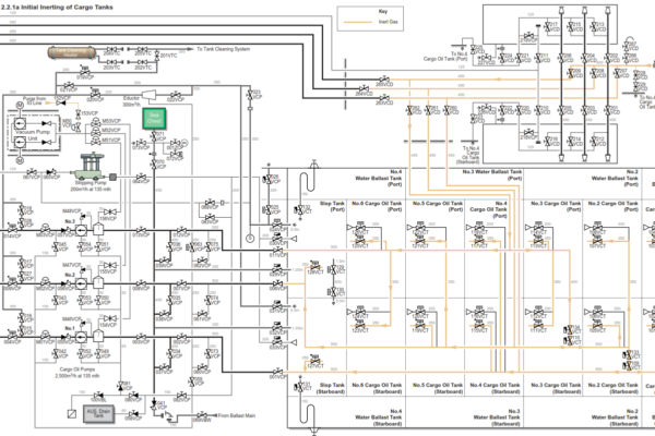
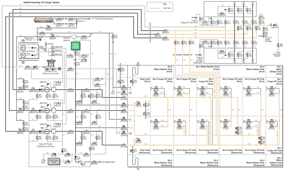
Under normal operating conditions the vessel is kept totally inerted. However, after refit or tank inspections some, or all, of the tanks may be gas free. Prior to any cargo operations all COTs must be inerted and this is normally completed en route to the loadport. Good quality IG must be supplied to the COTs to be inerted and each COT vented through the individual tank vents.
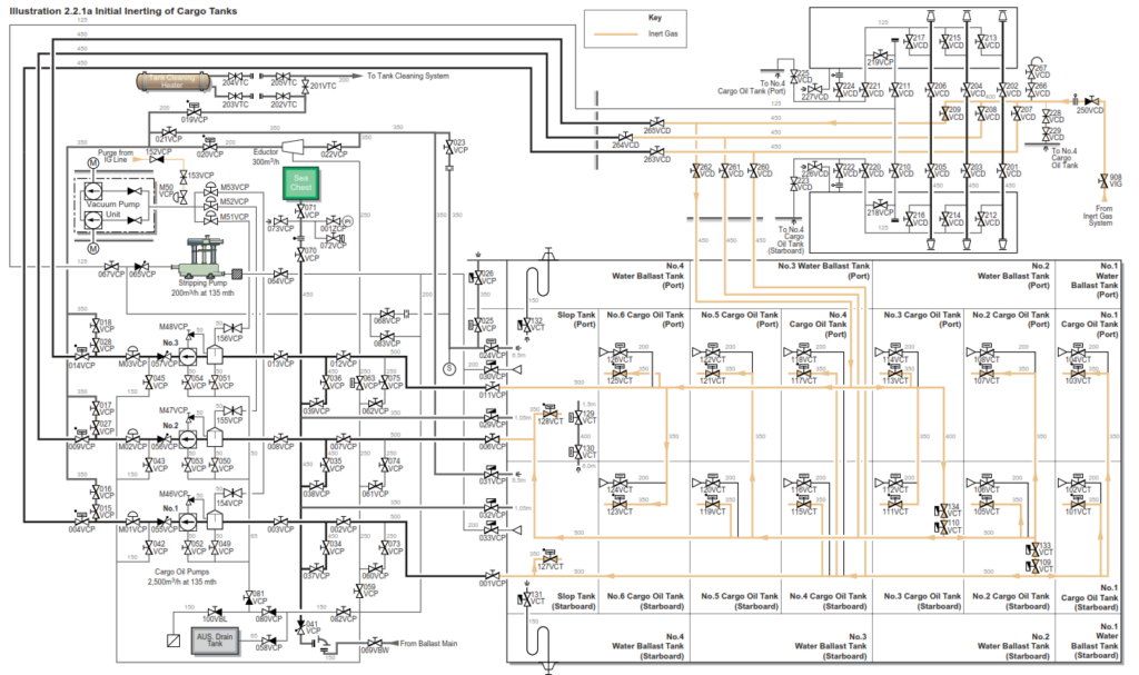
Inert gas is heavier than air, so the displacement method is recommended. This is achieved by introducing a steady flow of IG into the bottom of each COT at low pressure and displacing the air from the top the tank via the individual tank vent. It is normal to purge several tanks at the same time. The maximum number of tanks should be open whilst still maintaining a slight flow out of the tanks to atmosphere, as this will assist in better layering of the IG in the tanks. The quality of the vented tank atmosphere is monitored at regular intervals. When the oxygen content is below 8% O2 the COT is considered to be inerted. However, it is advisable to reduce the oxygen level to below 5% O2 if time allows, so increasing the margins of safety.
Assuming that all COTs are gas free.
a) Turn the the specticle piece connecting the IG supply main onto the cargo main into the open position which is located at the port side manifold area.
b) Check that the valve on the branch line connecting each cargo tank to the IG main is in the closed position.
c) Confirm that the IG plant is running.
| Position | Description | Valve |
| Open | Cross-connection from IG main to cargo main | 908VIG 250VCD |
| Open | Main cargo line valves allowing IG into No.3 bottom line | 209VCD 262VCD |
| Open | Bottom crossover valves into No.1 and No.2 lines | 133VCT 109VCT 134VCT 110VCT |
| Position | Description | Valve |
| Open | Cargo oil tank suction valves on all cargo tanks, including the slop tanks | 103VCT 101VCT 107VCT 105VCT 113VCT 111VCT 117VCT 115VCT 121VCT 119VCT 125VCT 123VCT 128VCT 127VCT |
| Closed | IG deck isolating valve | 902VIG |
| Open | Vent on each cargo tank |
d) With the IG plant running and the O2 content less than 5%, press the INERT GAS SUPPLY pushbutton on the IG control panel in the CCR. Inert gas will now be delivered to the selected tanks with the displaced atmosphere being vented out via the individual tank gas freeing vents.
e) Test the atmosphere of each tank at regular intervals with the portable gas monitoring equipment. When the oxygen content is less than 8% throughout each tank, it is then assumed that the tanks are fully inerted. If time allows, it is recommended to reduce the oxygen content to 5% or below. It may be necessary to throttle in on selected cargo tanks in order to get the oxygen content to the required level in the other tanks.
f) When all tanks are fully inerted, redirect the discharge from the IG plant to atmosphere by pressing the INERT GAS SUPPLY stop pushbutton on the IG control panel. Close the valves connecting the IG system to the cargo line system and all cargo suction/filling valves. Close the lids on the gas freeing tank vents. Turn the specticale piece into the closed position from the IG crossover to the cargo system.
| Position | Description | Valve |
| Set | IG discharge to atmosphere | |
| Close | Cargo oil tank suction valves on all cargo tanks, including the slop tanks | 103VCT 101VCT 107VCT 105VCT 113VCT 111VCT 117VCT 115VCT 121VCT 119VCT 125VCT 123VCT 128VCT 127VCT |
| Close | Main cargo line valves allowing IG into No.3 bottom line | 209VCD 262VCD |
| Close | Cross-connection from IG main to cargo system | 908VIG 250VCD |
| Close | Bottom crossover valves to No.1 and No.2 bottom lines | 133VCT 109VCT 134VCT 110VCT |
| Close | Cargo tank gas freeing vents on each tank |
g) Ensure the IG spade blanks on each tank are in the open position. Open the indivdiual tank isolating valves. Return the IG system to discharge onto the IG main and commence pressurising the system.
h) When normal operating pressure is reached in all tanks, shut down the IG plant and close the deck main isolating valve 902VIG.
USE WITH/WITHOUT VAPOUR EMISSION CONTROL (VEC)
New legislation in some ports may demand that the vessel operates in VEC mode. This basically involves connecting a vapour return arm to the IG main at the manifold so that the entire displaced COT atmosphere is processed ashore rather than being vented directly to atmosphere.
Most load ports at present allow venting to atmosphere. Where venting is permitted during loading, excess vapour is vented to atmosphere through the mast riser.
The ship’s maximum loading rate is contracted as 9,400m3/h, with a maximum loading rate to each wing tank of 2,879m3/h and 2,158m3/h for each slop tank.
Vapour Emission Control System
This system is provided to satisfy the requirements of IMO MSC/CIRC.585 and USCG regulations for vapour emission control systems CFR 46 Part 39. The system has the following components:
1. Inert Gas Line and Vent System. The vessel is fitted with two 450mm manifold valves port and starboard amidships, which are connected into the cargo oil tank IG main line. Two sets reducers of 450mm x 300mm are supplied for the vapour return line. Care must be taken to ensure that the pressure in the IG main remains within the operational parameters.
2. Oxygen content meter. The oxygen content is measured using a portable instrument type OX-226. Prior to commencing loading the oxygen content must be below 8% in all tanks.
3. Radar type level gauge for each tank which displays an ullage reading in the CCR on the CRT workstation display.
4. Vapour pressure alarm. This is mounted on the IG control panel in the CCR giving alarm indications for the vapour pressure in the following situations, extra low, low or high. Additionally, there is a readout display for the IG main line pressure and an alarm for power source failure to the panel. The alarms are also displayed on the bridge IG panel.
Alarm Set Points
Vapour pressure high: 1,260mmAq
Vapour pressure low: 100mmAq
5. An overfill system is also fitted as part of the VEC. An alarm panel is mounted in the CCR on the cargo control console providing the alarms for each cargo oil tank which activates at 98.5%. Indication of cargo tank high level is transmitted from the Saab TankRadar system. Additionally, there are power source to panel failure and system failure for the level gauge system indicated on the cargo console. Overfill alarm indication is given by a horn and revolving light on the compass deck, port side, in the CCR an alarm is indicated by a buzzer and light on the cargo control console.
6. Safety systems. The cargo tanks are protected against either overpressurisation or being placed under an excessive vacuum by individual tank combined PV valves. The Hi-Jet side of this unit lifts at 1,400mmAq, and the vacuum side lifts at -500mmAq; the maximum gas flow through the Hi-Jet is 1,960m3/h. A pressure and vacuum breaker is attached to the IG line and operates at a tank pressure of 1,610mmAq or vacuum of -700mmAq. The maximum gas flow through the breaker is 12,000m3/h.
To Load at a Shore Terminal with VEC
Prior to any cargo operations the following vapour recovery parameters must be established at the pre-transfer conference.
• Present vapour pressure in the cargo tanks.
• Lowest setting of the vessel’s vacuum relief valves.
• Highest setting of the vessel’s relief valves.
• The initial loading rate and the maximum flow rate of all concurrent cargo.
• The maximum vapour transfer the shore facility can handle, including both system and berth limitations.
• Types of vapours which will be discharged from the present as well previous cargoes.
• The maximum pressure drop from the cargo tanks to the vessel’s vapour manifold connection during the maximum cargo loading flow rate.
• The operating pressure to be maintained in the cargo tanks.
• The maximum and minimum vapour operating pressures.
• The facility’s alarm and trip set points for high and low pressures.
• Verify that all level alarms have been tested within the last 24 hours.
• Verify that all vapour recovery valves are in the correct position.
Procedure to Return Vapour to Shore during Cargo Operations
a) Verify that the IG deck isolating valve, 902VIG is shut.
b) Make sure the IG deck main is made common with all individual cargo oil tank IG spade pieces in the open position, the tank lids closed and the branch valves to each tank opened.
| Position | Description | Valve |
| Open | IG branch valves to No.1 COT | 911VIG 912VIG |
| Open | IG branch valves to No.2 COT | 921VIG 922VIG |
| Open | IG branch valves to No.3 COT | 931VIG 932VIG |
| Open | IG branch valves to No.4 COT | 941VIG 942VIG |
| Open | IG branch valves to No.5 COT | 951VIG 952VIG |
| Open | IG branch valves to No.6 COT | 961VIG 962VIG |
| Open | IG branch valves to slop tanks | 971VIG 972VIG |
c) Ensure that the yellow vapour connection piece is in place.
Check that the shore hose has a current certification of a pressure test and that it is free from any defects.
d) Connect the vapour hose, using a new joint if necessary, ensuring the hose is correctly supported.
e) Ensure that the control panel for the IG system in the CCR is switched on so that the IG main pressure can be monitored.
f) Open and close the IG main line drain valves to ensure all condensate has drained off.
f) Open the amidships manifold valve to which the vapour recovery arm is connected, either 904VIG, 905VIG, 906VIG or 907VIG.
g) Should the tank pressure drop to 100mmAq, the low pressure alarm will sound and it will be necessary to shut in the VEC manifold until loading has commenced or the flow rate is increased.
Cargo transfer operations are then carried out so that all vapour emissions are contained within a closed system. Ensure that tank pressures, flow rates and oxygen levels are constantly being monitored.
At a Shore Terminal without VEC
There will be occasions where, due to lack of shoreside vapour control systems, it will be necessary to carry out cargo transfers without their use.
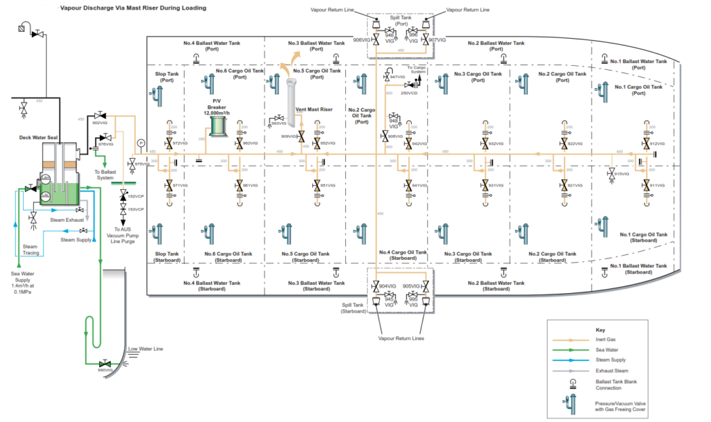
In this situation it will be necessary to make use of the vessel’s vent mast riser to control the tank pressure during loading.
As with the enclosed system operation the pre-transfer conference will require the same information with the exception of those items relating to the vapour recovery to the shore facility.
The vent mast riser valve 909VIG should be set to the OPEN position to ensure maximum flow through it during the loading. The vent mast riser is designed to release the vapour at a rate that will propel the released vapour away from the vessel’s decks and clear of any danger areas.
During the initial stages of loading when the flow rate will be at a minimum,
909VIG will be required to be manually adjusted to balance the discharge flow rate of IG being displaced by the cargo oil. As the loading rate is increased up to bulk flow, 909VIG will be required to be manually adjusted in order to control the IG pressure inside the tanks. The IG main pressure must be carefully monitored, account should be made for any fluctuations on the bulk loading rate, i.e., terminal rate reduction, pump stopping etc, which will affect the IG pressure and the % open position requirement of 909VIG.
During the use of the vent mast riser, care must be taken to ensure that changes in the climatic conditions, i.e. lightning or very calm conditions, do not interfere with the safety of the operations.
Procedure to Vent the Atmosphere of the Cargo Oil Tanks via the Mast Riser During Loading Operations
All valves are initially shut.
a) Verify that the IG deck isolating valve, 902VIG is shut.
b) Make sure the IG deck main is made common with all individual cargo oil tank IG spade pieces in the open position, the tank lids closed, and the branch valves to each tank opened.
| Position | Description | Valve |
| Open | IG branch valves to No.1 COT | 911VIG 912VIG |
| Open | IG branch valves to No.2 COT | 921VIG 922VIG |
| Open | IG branch valves to No.3 COT | 931VIG 932VIG |
| Open | IG branch valves to No.4 COT | 941VIG 942VIG |
| Open | IG branch valves to No.5 COT | 951VIG 952VIG |
| Open | IG branch valves to No.6 COT | 961VIG 962VIG |
| Open | IG branch valves to slop tanks | 971VIG 972VIG |
c) Open the vent mast riser valve 909VIG, its setting should be according to the chief officer/duty deck officer instructions.
d) Start loading operations.
e) Monitor the IG main pressure regularly, manually adjusting 909VIG accordingly.
INERT GAS OPERATIONS DURING LOADING
Single Grade
During the loading operation the main IG plant is shut down and the tank pressure is controlled via the vent mast riser or the VEC manifold. See above diagram which shows the paths via the VEC. If the vapour is not being discharged via the VEC to shore, the vapour paths will be the same and vent via the vent mast riser.
Each individual tank isolating valve and spade blank in the IG system should be open with the tanks at normal operating pressure.
| Position | Description | Valve |
| Open | IG main vent riser but only if VEC not in use | 909VIG |
| or | ||
| Open | Open VEC manifold in use if VEC is being used | 907VIG 906VIG 905VIG or 904VIG |
Multigrade
The same basic principle applies to loading more than one grade, as each pair of wing tanks is connected to the same 450mm IG main by means of a 200mm crossover.
It is not possible to send more than one vapour to shore via the vapour recovery system at any one time. However, in the event of incompatible vapours each cargo tank is fitted with a combined PV valve and can be isolated from the IG main by closing the tank isolating valve.
Note: Prior to tank isolating valves being closed it is essential to ensure that the tank PV valves are operating correctly. A lever attached to each valve is provided for this purpose.
It should be noted that the main IG line (450mm) is restricted to a maximum gas flow rate of 12,000m3/h this being the venting capacity of the deck PV breaker.
| Using IG Line | One Manifold | Two Manifolds | Three Manifolds |
| One wing tank | 2,879m3/h | 2,879m3/h | 2,879m3/h |
| One pair COTs | 3,688m3/h | 5,758m3/h | 5,758m3/h |
| Two pair COTs separate segregations | 3,688m3/h | 7,376m3/h | 9,400m3/h |
| Three pair COTs separate segregations | 3,688m3/h | 7,376m3/h | 9,400m3/h |
| Port or starboard slop tanks | 2,158m3/h | 2,158m3/h | 2,158m3/h |
| Using Individual Hi-Jet | Hi-Jet Rate | USCG Required Rate |
| Per tank | 1,960m3/h | 1,568m3/h |
In the above loading rate situations both the main and stripping valves are open with the exception of the slop tanks. Should the stripping valve be closed on the main cargo tanks, then the rate per tank should be reduced by 721m3/h.
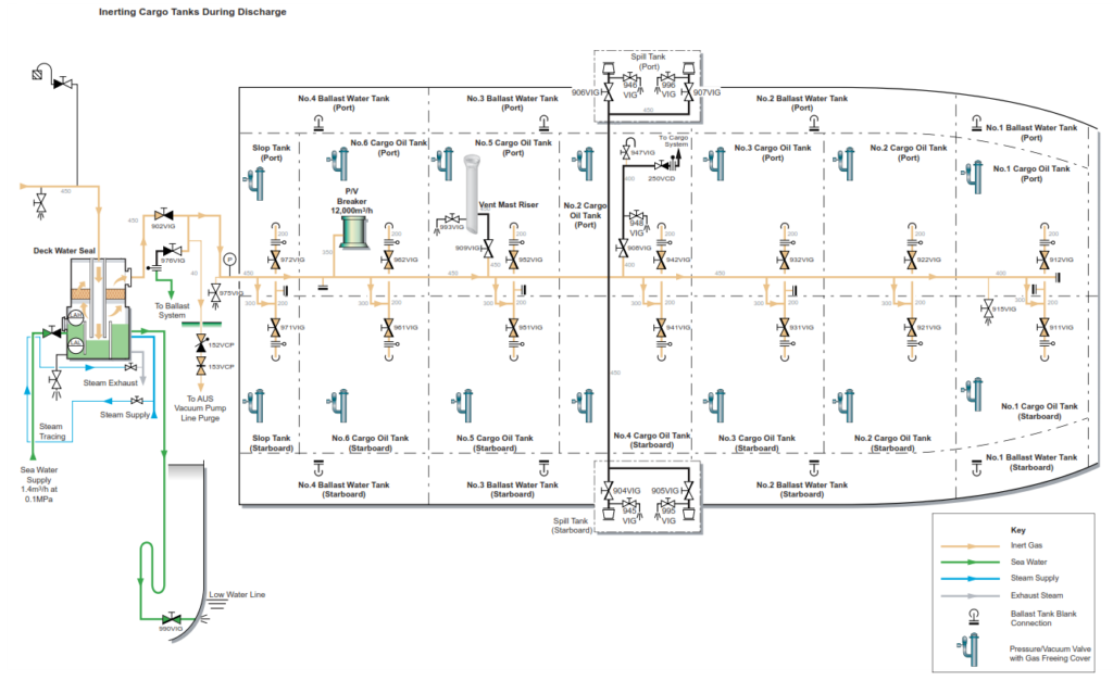
INERT GAS OPERATIONS DURING DISCHARGING
Single Grade
Part of the pre-discharge safety checks must be to ensure that the IG system is set up and the supply valves are open.
Prior to starting discharge it is necessary to start the IG plant with the system recirculating until the oxygen level is below 5%. When the quality of IG is satisfactory, regulate the supply of IG to the tanks by adjustment of the pressure controller, i.e., automatic control of the deck supply valve and the capacity control valves.
Start the cargo pumps and observe the pressure of the IG as the discharge rate increases.
The capacity of the flue gas system is 9,400m3/h. It is advisable to maintain the pressure of the inert gas between 5kPa and 9kPa during the discharge, particularly in the early stages. This will ensure that during the period of minimum ullage space, the cargo pumps can be utilised without the danger of creating a vacuum.
Procedure to Supply Inert Gas to the Cargo Oil Tanks During Discharge Operations
Single Grade
Ensure all COT spade blanks have been rotated to the open position and each COT IG isolating valve is checked to be in a locked open position. This is the normal operating set-up when the cargo tanks are in an inert condition
| Position | Description | Valve |
| Open | Deck isolating valve | 902VIG |
Adjust as required the set point for the pressure controller to maintain the required pressure in the cargo tanks. The maximum discharge rate whilst using three bottom lines is 7,500m3/h.
Multigrade
Where there is more than one grade and the vapours are compatible the procedure is the same as for a single grade.
Where vapours between grades are not compatible each grade will require to be discharged separately with the tank isolating valves on tanks of the grades not being discharged closed. The deck isolating valve will be open throughout and the IG pressure controller set point adjusted to maintain the required pressure in the cargo tanks.
Note: In this situation it is essential to ensure that the individual tank PV valves are operating correctly. A lever attached to each valve is provided for this purpose.