System described basis my present vessel
FULL DISCHARGE
The following factors are to be considered prior to a full discharge:
• Maximum available draught at the berth
• Maximum allowable freeboard on the berth
• Grade segregation, if carrying multiple grades
• Crude oil washing requirements
• Heavy weather ballast requirements
• Maintenance of satisfactory trim and stress
• Ballasting operations
When preparing the system to discharge cargo, it is important that all valves are in the closed position prior to setting the lines for discharge and all tank IG connections are set up as required.
a) All COW valves are to be closed.
b) Ensure that all overboard valves are closed and sealed and any elbow pieces are removed and spectacle blanks turned to the closed position.
c) The cargo pumping system and the IG plant is to be prepared for operation.
d) Open the main lines from the COTs to the main cargo pumps and then up to the manifolds.
e) Start the IG plant.
f) Open one set of COTs to each cargo oil pump (COP) and prime the separators.
g) Open the manifold valves that the discharge arms are connected to.
h) Start each COP and run at minimum speed, watching the back pressures carefully.
i) When pumps and pressures are balanced, debottom all tanks by at least 1m in preparation for crude oil washing. If it is intended that the slop tanks are to be used for crude oil washing, they should be discharged and refilled with fresh ‘dry’ crude oil.
j) Increase to full speed discharge as per the discharge plan and in agreement with the shore installation.
Note: During draining it may be necessary to reduce the speed of the cargo pump on the draining phase and closing in on its pneumatic controlled discharge valve, thereby increasing the back pressure and improving draining performance.
k) The ballast crossover line to the bottom cargo line is normally kept closed and blanked. The elbow bend between the cargo oil and ballast systems must be removed and the lines blanked.
l) The crossover valves between the cargo lines in No.2 and 3 cargo oil tanks can be opened to optimise COP performance, but care must be exercised. Top lines are normally kept isolated to improve draining performance.
m) When a cargo oil tank reaches a sounding of approximately 1.5m, the AUS vacuum pump system can be started and the automatic unloading system activated.
n) The bottom COW can be started as required when the selected tanks are drained.
o) Upon completion of discharge, the cargo lines must be drained to the shore tanks.
Procedure for Line Draining
This can be achieved by draining all lines with the stripping pump and pumping the drainings ashore via the MARPOL line. During draining of the lines, the vacuum in the cargo lines must be broken via vacuum breaker valve 228VCD,229VCD and crossover valves 207VCD, 208VCD, 209VCD. The drainings are discharged via the MARPOL line either directly ashore using the MARPOL line manifold valves or via one or more of the cargo manifold lines.
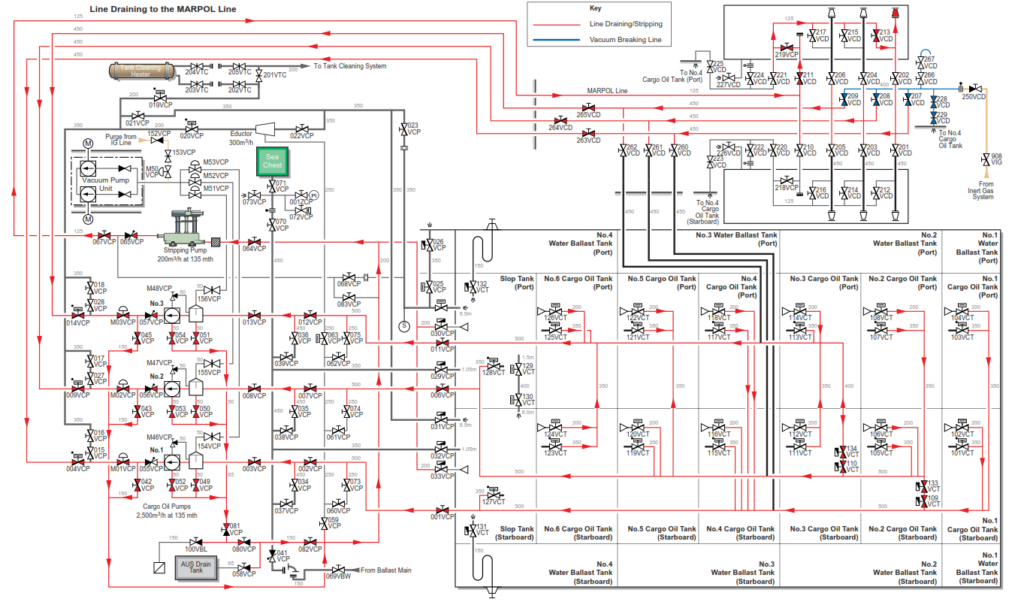
a) Set the MARPOL line valves for draining ashore via No.1 manifold.
| Position | Description | Valve |
| Open | MARPOL line block valves port or starboard | 211VCP 219VCP or 210VCP 218VCP |
| Open | No.1 manifold drain valve port or starboard | 213VCD or 212VCD |
b) Set the pump room valves for draining the lines.
| Position | Description | Valve |
| Open | No.1 top line block valve | 263VCD |
| Open | No.2 top line block valve | 264VCD |
| Open | No.3 top line block valve | 265VCD |
| Open | No.1 cargo oil pump discharge valve | 004VCP |
| Open | No.2 cargo oil pump discharge valve | 009VCP |
| Open | No.3 cargo oil pump discharge valve | 014VCP |
| Open | No.1 discharge pneumatic control valve | M01VCP |
| Open | No.2 discharge pneumatic control valve | M02VCP |
| Open | No.3 discharge pneumatic control valve | M03VCP |
| Open | Stripping pump connection to No.1 COP | 042VCP |
| Open | Stripping pump connection to No.2 COP | 043VCP |
| Open | Stripping pump connection to No.3 COP | 045VCP |
| Open | Stripping pump connection to No.1 COP and strainer | 049VCP 052VCP |
| Open | Stripping pump connection to No.2 COP and strainer | 050VCP 053VCP |
| Open | Stripping pump connection to No.3 COP and strainer | 051VCP 054VCP |
| Open | Stripping pump valves to COP drain line | 080VCP 081VCP 082VCP |
| Open | Stripping pump suction valve | 064VCP |
| Open | Stripping pump discharge to MARPOL line | 067VCP |
c) Start the stripping pump and observe the vacuum on the line.
Listen to the flow at the manifold. Open the vacuum breaking valves as required.
| Position | Description | Valve |
| Open | Vacuum breaker valves to No.4 COT | 228VCD 229VCD |
| Open | Crossover valves from vacuum breaker to No.1, 2 and 3 top lines | 207VCD 208VCD 209VCD |
d) On completion of line draining close all valves and agree ship/shore figures.
Segregated ballast loading should be started once bulk discharge has commenced and in accordance with the chief officer’s unloading plan, consistent with maintaining the trim and stress within acceptable limits.
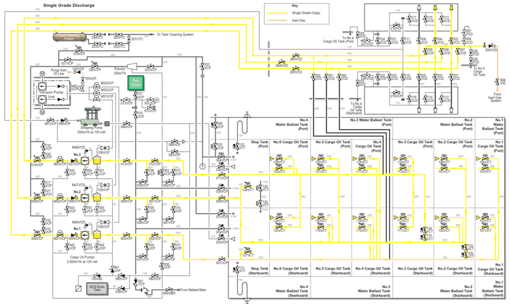
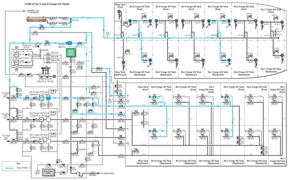
FULL DISCHARGE OF A SINGLE GRADE CARGO WITH COW OF BOTH SLOP TANKS, NO.2 AND NO.4 COTS
The following factors are to be considered prior to a full cargo discharge:
• Maximum available draught at the berth
• Maximum allowable freeboard on the berth
• Grade segregation, if carrying multiple grades
• Crude oil washing requirements
• Heavy weather ballast requirements
• Maintenance of satisfactory trim and stress
• Ballasting operations
When preparing the system to discharge cargo, it is important that all valves are in the closed position prior to setting the lines for discharge and all tank IG connections are set up as required.
a) Initially all the cargo valves should be shut. The engineering department will carry out the initial preparation work for the running of the IG system and make preparations for warming through the cargo oil pumps (COP). Set up the cargo system and tanks ready to commence discharge of cargo using in this scenario, all three cargo pumps after the initial line clearance.
| Position | Description | Valve |
| Open | Deck isolating valve and start IG system | 902VIG |
| Open | Forward crossover valves | 109VCT 133VCT 110VCT 134VCT |
| Open | Pump room bulkhead master block valves | 001VCP 006VCP 011VCP |
| Open | Pump room intermediate block valves | 002VCP 007VCP 012VCP |
| Open | No.1, 2 and 3 COP suction valves | 003VCP 008VCP 013VCP |
| Open | No.4 COT suction valves | 107VCT 115VCT |
| Closed | No.1, 2 and 3 COP pneumatic controlled discharge valve to top line | M01VCP M02VCP M03VCP |
| Position | Description | Valve |
| Open | No.1, 2 and 3 COP discharge valves | 004VCP 009VCP 014VCP |
| Open | Top line block valves | 263VCD 264VCD 265VCD |
b) Prime the COP separators, if necessary use the AUS vacuum pumps. The float valve inside each separator should stop any carryover from the cargo tanks into the AUS vapour line.
c) When the shore terminal confirm they are ready to receive cargo.
| Position | Description | Valve |
| Open | Manifold valves that the discharge valves are connected to | 202VCD 204VCD 206VCD if port side OR 201VCD 203VCD 205VCD if starboard side |
If the loading arms are not connected to all manifolds, then the discharge lines can be made common at the manifold crossover by opening valves 207VCD,208VCD and 209VCD.
During the initial line clearance phase, it will not be necessary to start all three COPs at the same time if all of the manifold connections are not being used. In this scenario with only two lines from ashore, only No.1 and 2 COPs will be used to carry out the testing and security check of the lines and the initial line clearance, No.3 COP will be brought one line when bulk discharge is ready to commence.
d) Start No.1 and No.2 COPs . As the pump(s) speed is brought up to minimum rpm by the duty engineer, observe that the pump discharge pressure does not rise above 0.5MPa. If necessary open the COPs pneumatic control discharge valve to control the pressure. Open a drop valve on the discharge header if a manifold valve is not yet open.
e) Commence the discharge line clearance at minimum speed, carrying out all safety and integrity checks after each pump is started. Close the drop valve if one had been opened.
f) Debottom all tanks by at least 1m to remove any wet crude once the system has been proved.
g) Once the system has been proved, and with the shore installation’s agreement, increase the pump speed until the maximum permitted back pressure or flow rate is achieved. Start the third COP as necessary in order to obtain the maximum allowable output. Close in on the appropriate tanks in order to create the stagger according to the chief officers unloading plan. In this scenario the stagger is No.1, 4, 2, 5, 3, 6 and both slop tanks.
h) As the slop tanks approach the ullage for top washing, set up the fixed tank cleaning machines at the correct angles (130° to 40°) taking drive from No.1 COT and pump. Continue discharging the slop tanks to the draining level with the COPs. Close in on No.1 COP discharge to the top line to maintain at least 0.8MPa on the COW line.
| Position | Description | Valve |
| Open | No.1 COP discharge valve to the COW line | 016VCP 015VCP |
| Open | Pump room COW line isolating valves to tank cleaning machines | 019VCP 201VTC |
| Open | Slop tanks fixed tank washing machine valves | 016VTC 039VTC 040VTC |
| Close In | No.1 COP discharge to top line to maintain 0.8MPa on the COW main | 004VCP |
i) After top COW of the slop tanks is finished, return No.1 COP to continue discharging the slop tanks to their draining level, the automatic unloading system should be set up, also reduce the speed of No.2 and No.3 COPs for draining.
| Position | Description | Valve |
| Open | No.1 COP discharge valve | 004VCP |
| Close | No.1 COP discharge valve to the COW line | 016VCP 015VCP |
| Close | Pump room COW line isolating valves to tank cleaning machines | 019VCP 201VTC |
| Close | Slop tanks fixed tank washing machine valves | 016VTC 039VTC 040VTC |
j) Prepare to carry out the bottom COW of both slop tanks (40° to 0°).
k) Warm through the stripping pump, the pump will be used to maintain the slop tanks in a dry condition during bottom COW of both slop tanks, discharging via the MARPOL line to the manifold. Drive for the COW machines will be from No.1 COT and via No.1 COP.
l) With the cargo stripping pump ready for operation:
| Position | Description | Valve |
| Open | Stripping pump suction valve | 064VCP |
| Open | Stripping pump suction valves from the slop tanks | 030VCP 033VCP |
| Open | Stripping pump discharge to the MARPOL line | 067VCP |
| Open | MARPOL line to block valves to manifold, (port manifold in use) | 211VCD 219VCP |
| Open | MARPOL line to outboard on No.1 manifold valve | 213VCD |
| Close | Port and starboard slop tank main suction valves | 128VCT 127VCT |
m) Commence bottom COW of both slop tanks, closing in on the discharge valve from No.1 COP to maintain 0.8MPa on the COW main.
| Position | Description | Valve |
| Open | No.1 COP discharge valve to the COW line | 016VCP 015VCP |
| Open | Pump room COW line isolating valves to tank cleaning machines | 019VCP 201VTC |
| Open | Slop tanks fixed tank washing machine valves | 016VTC 039VTC 040VTC |
| Close In | No.1 COP discharge to top line to maintain 0.8MPa on the COW main | 004VCP |
n) On completion of COW and draining of the slop tanks, change over No.1 COP to No.1 COT and No.2 COP to No.2 COT. Return No.3 COP to discharging ashore from No.4 COT. Stop the stripping pump and close the line valves
| Position | Description | Valve |
| Close | No.1 COP discharge valves to COW line | 016VCP 015VCP |
| Close | Pump room COW line isolating valves to tank cleaning machines | 019VCP 201VTC |
| Position | Description | Valve |
| Close | Fixed tank washing machine valves | 016VTC 039VTC 040VTC |
| Close | Slop tank suction valves | 127VCT 128VCT |
| Open | No.1 COP discharge valve to top line | 004VCP |
| Open | No.1 COT suction valves | 101VCT 103VCT |
| Open | No.2 COT suction valves | 105VCT 107VCT |
| Open | No.4 COT suction valves | 115VCT 117VCT |
| Close | Stripping pump suction valve | 064VCP |
| Close | Stripping pump suction valves from the slop tanks | 030VCP 033VCP |
| Close | Stripping pump discharge to the MARPOL line | 067VCP |
| Close | MARPOL line to block valves to manifold, (port manifold in use) | 211VCD 219VCP |
| Close | MARPOL line to outboard on No.1 manifold valve | 213VCD |
During the bottom COW, ensure that the vessel is trimmed by the stern to facilitate stripping, approximately 3 to 4m. Terminal restrictions may restrict the maximum trim; in addition the vessel’s stability, stress and freeboard must be maintained within the permitted levels. Note the cargo tank suction valves are in wells aligned to the port side of the tanks.
Continue to discharge ashore all other bulk cargo using the maximum number of cargo pumps.
o) Refill the slop tanks with clean cargo to approximately 50% ullage, sufficient to cover the levelling line. Slowly open the slop tank main suctions and run in fresh crude, as necessary reducing the speed of No.1 and 3 COPs to allow the level to rise.
| Position | Description | Valve |
| Open | Slop tank main suction valves | 127VCT 128VCT |
p) On completion of recharging, shut the slop tank main suction valves and increase No.1 and No.3 COP to maximum. If sufficient ullage has not been attained in slop tanks, additional crude can be bled off to the slop tanks via the COP discharge to the eductor.
| Position | Description | Valve |
| Close | Slop tank main suction valves | 127VCT 128VCT |
q) When No.4 COTs reach the top wash ullage (COW angle 130° to 70°), set up No.1 COP to supply crude from No.1 COT via the COW line to the fixed tank cleaning machines. Maintain a pressure 0.8MPa on the COW main, closing in on the pump discharge valve to deck as required.
| Position | Description | Valve |
| Open | No.1 COP discharge valve to the COW line | 015VCP 016VCP |
| Open | Pump room COW line isolating valves to tank cleaning machines | 019VCP 201VTC |
| Open | Fixed tank washing machine valves on No.4 COTs | 013VTC 031VTC 032VTC 030VTC |
| Close In | No.1 COP discharge valve to the top line | 004VCP |
r) When top COW of No.4 COTs is complete, continue discharging No.4 COTs to the draining level.
| Position | Description | Valve |
| Close | No.1 COP discharge valve to the COW line | 015VCP 016VCP |
| Close | Pump room COW line isolating valves to tank cleaning machines | 019VCP 201VTC |
| Close | Fixed tank washing machine valves on No.4 COTs | 013VTC 031VTC 032VTC 030VTC |
| Open | No.1 COP discharge valve to the top line | 004VCP |
s) When No.2 COTs reach the top wash ullage (COW angle 130° to 70°), set up No.2 COP to supply crude from No.4 COT via the COW line to the fixed tank cleaning machines. Maintain a pressure 0.8MPa on the COW main, closing in on the pump discharge valve to deck as required.
| Position | Description | Valve |
| Open | No.2 COP discharge valve to the COW line | 017VCP 027VCP |
| Open | Pump room COW line isolating valves to tank cleaning machines | 019VCP 201VTC |
| Position | Description | Valve |
| Open | Fixed tank washing machine valves on No.2 COTs | 011VTC 025VTC 026VTC 024VTC |
| Close In | No.2 COP discharge valve to the top line | 009VCP |
t) When top COW of No.2 COTs is complete, continue discharging No.2 COTs to the draining level.
| Position | Description | Valve |
| Close | No.2 COP discharge valve to the COW line | 017VCP 027VCP |
| Close | Pump room COW line isolating valves to tank cleaning machines | 019VCP 201VTC |
| Close | Fixed tank washing machine valves on No.4 COTs | 011VTC 025VTC 026VTC 024VTC |
| Open | No.2 COP discharge valve to the top line | 009VCP |
u) As the first set of COTs in the stagger, No.1 and 4 approach the draining level, close the forward crossover valves 133VCT and 109VCT. Continue discharging No.2, 3, 5 and 6 COTs from No.2 and 3 COPs which are still cross connected via forward crossover valves 134VCT and 110VCT.
v) At the draining level for No.1 and 4 COTs set the AUS system into automatic operation. Strip out both tanks, close the main suction valves on both tank, leaving the stripping suction valve on each tank open.
| Position | Description | Valve |
| Close | Forward crossover valves in No.2 COT | 133VCT 109VCT |
| Close | No.1 and 4 COT main suction valves | 103VCT 101VCT 117VCT 115VCT |
| Open | No.1 and 4 COT stripping suction valves | 104VCT 102VCT 118VCT 116VCT |
| Open | No.2 COP discharge valve to the top line | 009VCP |
w) On completion of stripping of No.1 COTs, and with a manual dip indicating they are empty, close the stripping suction valves. Continue stripping No.4 COTs and prepare to carry out a bottom COW of the No.4 COTs when they are stripped out. Suction for COW is taken from the starboard slop tank via No.1COP. Stripping will be via the stripping eductor returning to the starboard slop tank. Reduce the speed of No.1 COP during the transfer from suction from No.4 COTs to the starboard slop tank.
x) Set up No.1 COP to provide drive fluid to the tank cleaning machines for No.4 COT and shut No.1 discharge valve to the top line to maintain at least 0.8MPa on the COW line.
| Position | Description | Valve |
| Close | No.1 COT stripping suction valves | 104VCT 102VCT |
| Open | No.4 COT stripping suction valves | 118VCT 117VCT |
| Open | No.1 COP suction from the starboard slop tank | 032VCP 037VCP 034VCP |
| Close | No.1 bottom suction block valve | 002VCP |
| Open | Eductor drive inlet and outlet valve and discharge to starboard slop tank | 020VCP 022VCP 031VCP |
| Open | No.1 COP discharge valves to COW line | 015VCP 016VCP |
| Close | No.1 COP discharge to the top line | 004VCP |
| Open | Pump room COW line isolating valves to tank cleaning machines | 019VCP 201VTC |
| Open Slowly | Fixed tank washing machine valves on No.4 COTs | 013VTC 031VTC 032VTC 030VTC |
| Open | Eductor suction from No.1 bottom line | 063VCP 060VCP 073VCP |
y) Bottom wash and drain No.4 COTs, as necessary shutting and opening the stripping suction valve on the starboard tank in order that suction will not be lost with a resultant accumulation of cargo oil in the port tank. This is due to half of the flow into the starboard tank from the COW machines as compared to the port tank.
z) On completion of bottom COW, reduce the speed on No.1 COP and change over to discharge the starboard slop tank to shore from the main suction, close all valves to the tank cleaning machines.
| Position | Description | Valve |
| Open | No.1 COP discharge valve to the top line | 004VCP |
| Close | No.1 COP discharge valve to the COW line | 015VCP 016VCP |
| Close | Pump room COW line isolating valves to tank cleaning machines | 019VCP 201VTC |
| Open | Slop tank main suction valve and bottom block valve | 127VCT 002VCP |
| Close | No.1 COP stripping suction valves from the starboard slop tank | 032VCP 037VCP 034VCP |
| Close | Eductor suction from No.1 bottom line | 063VCP 060VCP 073VCP |
| Close | Eductor drive inlet and outlet valve and discharge to starboard slop tank | 020VCP 022VCP 031VCP |
aa) On completion of stripping the starboard slop tank, No.1 COP can be shut down.
Shutting down No.1 COP should coincide with the stagger in the discharge, whereby No.2 and 5 COTs should be approaching their stripping stage. At this point the forward crossover valves 110VCP and 134VCP should be shut, allowing No.2 pump to strip No.2 and 5 COTs and conduct a COW of No.2 COTs. No.3 COP will continue on bulk discharge from No.3 and 6 COTs.
bb) When No.5 COTs reach their stripping stage, close the main suctions on No.2 and 5 and leave the stripping suctions open. Shut the stripping suctions on No.5 COT when they are dry and the manual dip confirms they are empty. Continue stripping No.2 COTs down to the level where they are almost dry, then set up for the bottom COW of these tanks via No.2 COP, taking the drive for the COW machines and eductor from the port slop tank.
| Close | No.2 COP stripping suction valves from the port slop tank | 029VCP 038VCP 035VCP |
| Close | Eductor drive inlet, outlet and discharge to the port slop tank | 020VCP 022VCP 023VCP 024VCP |
ee) On completion of stripping the port slop tank No.2 COP can be shut down.
Shutting down No.2 COP should coincide with the stagger in the discharge, whereby No.3 and 6 COTs should be approaching their stripping stage. Continue discharging these tanks down to their stripping level, shutting the main suctions valves and leaving the stripping valves open.
| Position | Description | Valve |
| Close | No.3 and 6 COT main suction valves | 113VCT 111VCT 125VCT 123VCT |
| Open | No.3 and 6 COT stripping suction valves | 114VCT 112VCT 126VCT 124VCT |
| Position | Description | Valve |
| Close | No.5 COT stripping suction valves | 122VCT 120VCT |
| Open | No.2 COT stripping suction valves | 108VCT 106VCT |
| Open | No.2 COP suction from the port slop tank | 029VCP 038VCP 035VCP |
| Close | No.2 bottom suction block valve | 007VCP |
| Open | Eductor drive inlet and outlet valve and discharge to port slop tank | 020VCP 022VCP 023VCP 024VCP |
| Open | No.2 COP discharge valves to COW line | 017VCP 027VCP |
| Close | No.2 COP discharge to the top line | 009VCP |
| Open | Pump room COW line isolating valves to tank cleaning machines | 019VCP 201VTC |
| Open Slowly | Fixed tank washing machine valves on No.2 COTs | 011VTC 025VTC 026VTC 024VTC |
| Open | Eductor suction from No.2 bottom line | 063VCP 061VCP 074VCP |
cc) Bottom wash and drain No.2 COTs, as necessary shutting and opening the stripping suction valve on the starboard tank in order that suction will not be lost with a resultant accumulation of cargo oil in the port tank. This is due to half of the flow into the starboard tank from the COW machines as compared to the port tank.
dd) On completion of bottom COW, reduce the speed on No.2 COP and change over to discharge the port slop tank to shore from the main suction, close all valves to the tank cleaning machines.
| Position | Description | Valve |
| Open | No.2 COP discharge valve to the top line | 009VCP |
| Close | No.2 COP discharge valve to the COW line | 017VCP 027VCP |
| Close | Pump room COW line isolating valves to tank cleaning machines | 019VCP 201VTC |
| Open | Port slop tank main suction valve and bottom block valve | 128VCT 007VCP |
| Close | No.2 COP stripping suction valves from the port slop tank | 029VCP 038VCP 035VCP |
| Close | Eductor drive inlet, outlet and discharge to the port slop tank | 020VCP 022VCP 023VCP 024VCP |
ee) On completion of stripping the port slop tank No.2 COP can be shut down.
Shutting down No.2 COP should coincide with the stagger in the discharge, whereby No.3 and 6 COTs should be approaching their stripping stage. Continue discharging these tanks down to their stripping level, shutting the main suctions valves and leaving the stripping valves open.
| Position | Description | Valve |
| Close | No.3 and 6 COT main suction valves | 113VCT 111VCT 125VCT 123VCT |
| Open | No.3 and 6 COT stripping suction valves | 114VCT 112VCT 126VCT 124VCT |
ff) On completion of final draining in No.3 and No.6 COTs and when a manual dip confirms that they are empty, stop No.3 COP.
The vessel is now ready to carry out draining of all lines as explained earlier in the blog. .
gg) Drain the lines and pumps using the stripping pump, discharging up the MARPOL line to the appropriate shore hose.
hh) On completion of line draining, close all valves and agree ship/shore figures.
Segregated ballast loading should be started as stated in the chief officer’s discharging plan, consistent with maintaining the trim and stress within acceptable limits.
After the final figures have been agreed, final adjustment to the ballasting can now be carried out in order to bring the ship into the required departure trim condition.
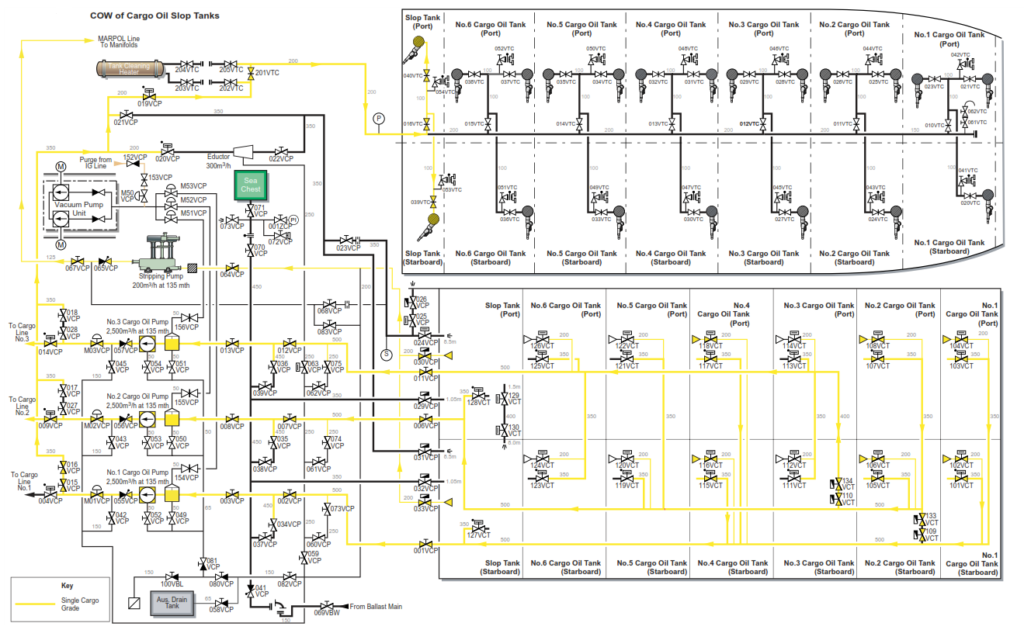
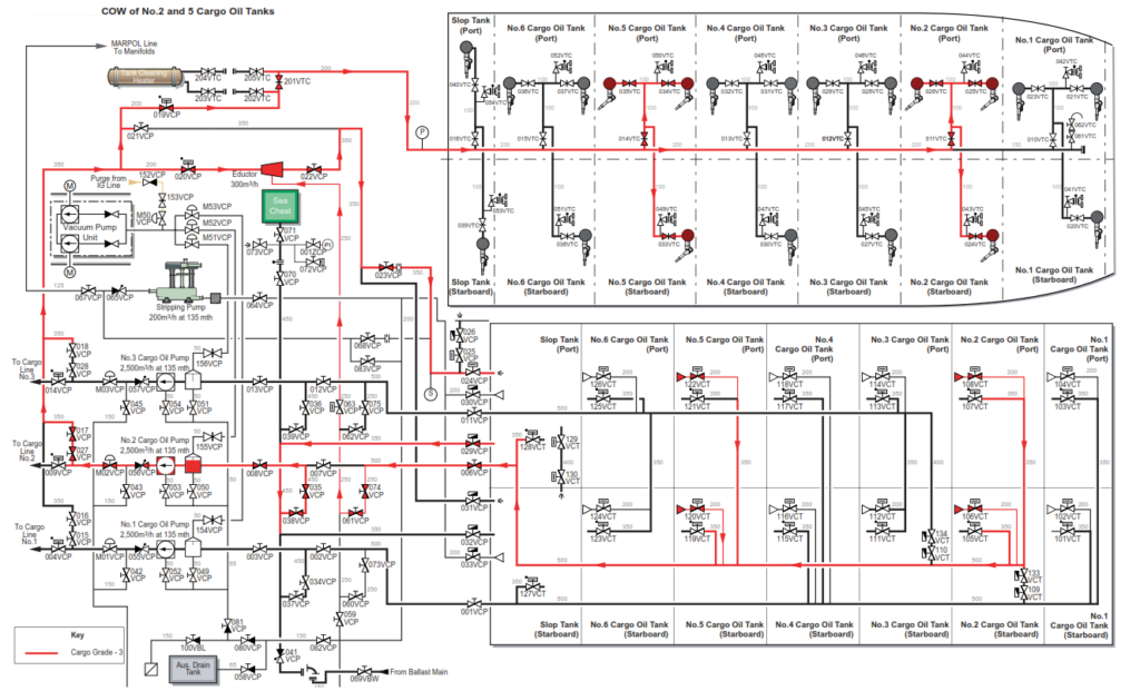
DISCHARGING A THREE GRADE CARGO WITH 100% COW, PIPELINE ADMIXTURE AND ONE VALVE SEPARATION ACCEPTABLE
Prior to arrival at the discharge port, a cargo plan shall be completed covering all aspects of the proposed discharging operation. This will ensure that the stability, stress, draught and trim are all within acceptable levels throughout the discharge, and comply at all times with terminal restrictions.
The following factors are to be considered prior to discharge:
• Maximum available draught at the berth
• Maximum allowable freeboard on the berth
• Grade segregation
• Crude oil washing requirements
• Heavy weather ballast requirements
• Maintenance of satisfactory trim and stress
• Ballasting operations
When preparing the system to discharge cargo, it is important that all valves are in the closed position prior to setting the lines for discharge and all tank IG connections are set up as required.
In the following case example it is assumed that the parcels are segragated as follows:
Group 1
No.1, 4 COT and the starboard slop tank
Group 2
No.2, 5 COT and the port slop tank
Group 3
No.3 and 6 COT
Ship/shore safety checklists must be completed prior to starting cargo discharge. Additionally, the cargo system valve line up should be double checked before commencing the discharge.
a) Initially all the cargo valves should be shut. The engineering department will carry out the initial preparation work for the running of the IG system and make preparations for warming through the cargo oil pumps (COP). Set up the cargo system and tanks ready to commence discharge of cargo. The intention is to discharge the port slop tank with No.2 COP and line, No.3 COT with No.1 COP and line and the starboard slop tank using No.1 COP and line.
Segregated ballast loading should be started in accordance with the chief officer’s discharging plan, consistent with maintaining the trim and stress within acceptable limits.
| Position | Description | Valve |
| Open | Deck isolating valve and start IG system | 902VIG |
| Open | Pump room bulkhead master valves | 001VCP 006VCP 011VCP |
| Open | Pump room intermediate block valves | 002VCP 007VCP 012VCP |
| Open | COP suction valves | 003VCP 008VCP 013VCP |
| Open | COP discharge valves to top line | M01VCP M02VCP M03VCP |
| Open | Pumproom top line isolating valves | 004VCP 009VCP 014VCP |
| Open | Top line block valves | 263VCD 264VCD 265VCD |
| Open | No.3 COTs suction valves | 111VCT 113VCT |
| Open | Both slop tank suction valves | 127VCT 128VCT |
b) When the shore terminal confirm they are ready to receive cargo open the manifolds the lines are connected to, then start each COP.
| Position | Description | Valve |
| Open | Manifold valves that the discharge hoses are connected to | 202VCD 204VCD 206VCD if port side or 201VCD 203VCD 205VCD if starboard side |
c) Commence the discharge at minimum speed, carrying out all safety and integrity checks after each pump is started, then debottom all tanks by at least 1m to remove any wet crude once the system has been proved.
d) Once the system has been proved, and with the shore installation’s agreement, increase the pump speed until the maximum agreed back pressure or flow rate is achieved.
e) Both slop tanks should be discharged directly to draining level.
| Position | Description | Valve |
| Close | Slop tank main suction valves | 127VCT 128VCT |
| Open | No.1 COT suction valves | 101VCT 103VCT |
| Open | No.5 COT suction valves | 119VCT 121VCT |
| Open | No.2 COP discharge valves to COW line | 017VCP 027VCP |
| Open | Pump room COW line isolating valves to tank cleaning machines | 019VCP 201VTC |
| Open | Port and starboard slop tank fixed tank washing machine valves | 016VTC 040VTC |
| Close | Vary position of No.2 COP isolating valve to top line | 009VCP |
| Open | Port slop tank stripping suction valve | 030VCP |
| Open | Stripping pump suction and discharge valves | 067VCP 064VCP |
| Open | MARPOL line valves to manifold being discharged from | 211VCD 219VCD 215VCD if port side or 210VCD 218VCD 214VCD if starboard side |
The automatic draining system should be started up when the first tank reaches a 1.5m sounding. Drain the starboard slop using No.1 COP then change over the pump suction to No.1 COT. Drain the port slop tank then change over the pump suction to No.5 COT. At this point set up the fixed tank cleaning machine at the correct angle (130° to 0°) to COW the port slop tank, taking drive from No.5 COT and draining using the stripping pump via the MARPOL line. Shut in No.2 top line isolating valve to maintain at least 0.8MPa on the COW line if required during the wash.
f) Start the stripping pump and carry out a full COW of the port slop tank. On completion of COW stop the stripping pump and prepare to COW the starboard slop tank using No.1 COP and line. Return No.2 COP to full discharge from No.5 COT.
| Position | Description | Valve |
| Open | No.2 COP discharge valves to COW line | 017VCP 027VCP |
| Close | Pump room COW line isolating valves to tank cleaning machines | 019VCP 201VTC |
| Close | Port slop tank fixed tank washing machine valves | 016VTC 040VTC |
| Open | No.2 COP isolating valve to top line | 009VCP |
| Close | Port slop tank stripping suction | 030VCP |
| Close | Stripping suction valve | 064VCP |
| Close | MARPOL line valve to manifold being discharged from | 215VCD if port side or 214VCD if starboard side |
g) Set up to COW the starboard slop tank taking the drive fluid from No.1 COP and No.1 COT, draining the slop tank with the stripping pump and discharging up the MARPOL line to No.1 manifold. Start the stripping pump
| Position | Description | Valve |
| Open | No.1 COP discharge valves to COW line | 015VCP 016VCP |
| Close | No.1 COP isolating valve to top line | 004VCP |
| Open | Pump room COW line isolating valves to tank cleaning machines | 019VCP 201VTC |
| Open | Starboard slop tank fixed tank washing machine valves | 016VTC 039VTC |
| Open | Starboard slop tank stripping suction valve | 033VCP |
| Open | Stripping pump suction valve | 064VCP |
| Open | Stripping pump discharge valves via the MARPOL line to the hose connected to No.1 line port or starboard | 213VCD if port side or 212VCD if starboard side |
h) On completion of COW return No.1 COP to discharging ashore from No.1 COT, stop the stripping pump. Drain the COW and MARPOL lines back to the starboard slop tank then slowly open the main suction to the starboard slop tank, running back from No.1 COT until the tank is 50% full.
| Position | Description | Valve |
| Close | No.1 COP discharge valves to COW line | 015VCP 016VCP |
| Open | No.1 COP isolating valve to top line | 004VCP |
| Open | Stripping pump return valve from discharge to suction side of pump | 083VCP |
| Open | COW line drain valves to starboard slop tank | 021VCP 031VCP |
| Close | Pump room COW line isolating valves to tank cleaning machines after draining | 019VCP 201VTC |
| Close | Starboard slop tank fixed tank washing machine valves | 016VTC 039VTC |
| Close | Starboard slop tank stripping suction valve | 033VCP |
| Close | Stripping pump suction valve | 064VCP |
| Close | Stripping pump discharge valves via the MARPOL line to the hose connected to No.1 line port or starboard | 211VCD 219VCD 213VCD if port side or 210VCD 218VCD 212VCD if starboard side |
| Close | Stripping pump return valve from discharge to suction side of pump | 083VCP |
| Close | COW line drain valves to starboard slop tank | 021VCP 031VCP |
i) Set up to run from No.3 COT to port slop tank until the tank is 50% full. Set up to run back from No.1 COT to starboard slop tank until the tank is 50% full.
| Position | Description | Valve |
| Open | Port slop tank stripping suction valve | 030VCP |
| Open | Stripping line valves from No.3 line to port slop tank | 075VCP 062VCP 059VCP |
| Open | Starboard slop tank main suction valve | 127VCT |
j) On completion of running back continue on full discharge from No.1 COT, No.3 COT and No.5 COT until the next tanks are ready for top washing.
| Position | Description | Valve |
| Open | Port slop tank stripping suction valve | 030VCP |
| Open | Stripping line valves from No.3 line to port slop tank | 075VCP 062VCP 059VCP |
| Open | Starboard slop tank main suction valve | 127VCT |
k) As No.3 COT approaches the ullage for top COW set up the fixed tank cleaning machines at the correct angle (130° to 70°) ready to COW taking drive fluid from No.3 COT. Close in No.3 top line isolating valve as necessary to maintain 0.8MPa. On completion of top COW continue discharge of No.3
COT starting the automatic draining system when the ullage approaches draining level. Partially drain the tank.
| Position | Description | Valve |
| Open | No.3 COP discharge valves to COW line | 018VCP 028VCP |
| Open | Pump room COW line isolating valves to tank cleaning machines | 019VCP 201VTC |
| Open | No.3 COT tank fixed tank washing machine valves | 012VTC 027VTC 028VTC 029VTC |
| Open | No.3 COT stripping suction valves | 112VCD 114VCD |
| Close | No.3 COP isolating valve to top line | 014VCP |
| Close | No.3 COT main suction valves | 111VCT 113VCT |
| Close | Pump room COW line isolating valves to tank cleaning machines | 019VCP |
| Close | No.3 COP discharge valves to COW line | 018VCP 028VCP |
l) Now set up and bottom COW No.3 COT using No.3 COP re- cycling on the port slop tank for drive fluid and draining with the eductor.
| Position | Description | Valve |
| Open | No.3 COP discharge valves to COW line | 018VCP 028VCP |
| Open | Pump room COW line isolating valves to tank cleaning machines | 019VCP 201VTC |
| Open | No.3 COT tank fixed tank washing machine valves | 012VTC 027VTC 028VTC 029VTC |
| Close | No.3 COP isolating valve to top line | 014VCP |
| Close | No.3 manifold valve | 205VCD or 206VCD |
| Close | No.3 COP suction intermediate block valve | 012VCP |
| Open | No.3 COP suction line to port slop tank | 036VCP 039VCP 029VCP |
| Open | No.3 COP discharge valves to the port slop tank | 020VCP 022VCP 023VCP 024VCP |
| Open | Eductor suction line to No.3 bottom line | 063VCP 062VCP 075VCP |
| Open | No.3 COT stripping suction valves | 112VCT 114VCT |
m) On completion of COW drain COW line back to the slop tank. Change over No.3 COP to discharging ashore from No.6 COT.
| Position | Description | Valve |
| Close | No.3 COP discharge valves to COW line | 018VCP 028VCP |
| Close | Pump room COW line isolating valves to tank cleaning machines | 019VCP 201VTC |
| Open | No.3 COP isolating valve to top line | 014VCP |
| Close | No.3 COT tank fixed tank washing machine valves | 012VTC 027VTC 028VTC 029VTC |
| Open | No.3 manifold valve | 205VCD or 206VCD |
| Open | No.3 COP suction intermediate block valve | 012VCP |
| Position | Description | Valve |
| Close | No.3 COP suction line to port slop tank | 036VCP 039VCP 029VCP |
| Close | No.3 COP discharge valves to the port slop tank | 020VCP 022VCP 023VCP 024VCP |
| Close | Eductor suction line to No.3 bottom line | 063VCP 062VCP 075VCP |
| Close | No.3 COT stripping suction valves | 112VCT 114VCT |
| Open | No.6 COT main suction valves | 123VCT 125VCT |
n) When No.5 COT reaches the draining level, drain with No.2 COP using the automatic stripping system then change over to discharge from No.2 COT. Discharge No.1 COT to the draining level then set up and COW No.1 COT using No.1 COP, re- cycling on the starboard slop tank for drive fluid and the eductor for draining
Note: During the discharge of No.2 COT adjust the pump speed to ensure that COW of No. 6 COT is completed, and that the discharge of the port slop tank and a transfer of 1,000m3 to port slop tank from No. 2 COT all take place before the draining level is reached in No.2 COT.
| Position | Description | Valve |
| Open | No.1 COP discharge valves to COW line | 015VCP 016VCP |
| Open | Pump room COW line isolating valves to tank cleaning machines | 019VCP 201VTC |
| Open | No.1 COT tank fixed tank washing machine valves | 010VTC 020VTC 021VTC 022VTC |
| Close | No.1 COP isolating valve to top line | 004VCP |
| Close | No.1 manifold valve either port or starboard whichever the discharge hose is connected to | 202VCD or 201VCD |
| Close | No.1 COP suction intermediate block valve | 002VCP |
| Open | No.1 COP suction line to starboard slop tank | 032VCP 034VCP 037VCP |
| Position | Description | Valve |
| Open | No.1 COP discharge valves to the starboard slop tank | 020VCP 022VCP 031VCP |
| Open | Eductor suction line to No.1 bottom line | 063VCP 060VCP 073VCP |
| Open | No.1 COT stripping suction valves | 101VCT 103VCT |
| Close | No.5 COT suction valves | 119VCT 120VCT 121VCT 122VCT |
| Open | No.2 COT suction valves | 105VCT 106VCT 107VCT 108VCT |
o) On completion of COW, drain the COW lines to the starboard slop tank and change over to full discharge from No.4 COT
| Position | Description | Valve |
| Close | No.1 COP discharge valves to COW line | 015VCP 016VCP |
| Close | Pump room COW line isolating valves to tank cleaning machines | 019VCP 201VTC |
| Close | No.1 COT tank fixed tank washing machine valves | 010VTC 020VTC 021VTC 022VTC |
| Open | No.1 COP isolating valve to top line | 004VCP |
| Open | No.1 manifold valve either port or starboard whichever the discharge hose is connected to | 202VCD or 201VCD |
| Open | No.1 COP suction intermediate block valve | 002VCP |
| Close | No.1 COP suction line to starboard slop tank | 032VCP 034VCP 037VCP |
| Close | No.1 COP discharge valves to the starboard slop tank | 020VCP 022VCP 031VCP, |
| Close | Eductor suction line to No.1 bottom line | 063VCP 060VCP 073VCP |
| Position | Description | Valve |
| Close | No.1 COT stripping suction valves | 101VCT 103VCT |
| Open | No.4 COT main suction valves | 115VCT 117VCT |
p) Continue discharge of No.6 COT starting the automatic draining system when the ullage approaches draining level. Partially drain the tank then set up and COW No.6 COT using No.3 COP re-cycling on the port slop tank and draining with the eductor.
| Position | Description | Valve |
| Open | No.6 COT stripping suction valves | 124VCT 126VCT |
| Close | No.6 COP main suction valves | 123VCT 125VCT |
q) Carry out a full COW of No.6 COT.
| Position | Description | Valve |
| Open | No.3 COP discharge valves to COW line | 018VCP 028VCP |
| Open | Pump room COW line isolating valves to tank cleaning machines | 019VCP 201VTC |
| Open | No.6 COT tank fixed tank washing machine valves | 015VTC 033VTC 034VTC 035VTC |
| Close | No.3 COP isolating valve to top line | 014VCP |
| Close | No.3 manifold valve either port or starboard whichever the discharge hose is connected to | 206VCD or 205VCD |
| Close | No.3 COP suction intermediate block valve | 012VCP |
| Open | No.3 COP suction line to port slop tank | 036VCP 038VCP 029VCP |
| Open | No.3 COP discharge valves to the port slop tank | 020VCP 022VCP 023VCP 024VCP |
| Open | Eductor suction line to No.3 bottom line | 063VCP 062VCP 075VCP |
| Position | Description | Valve |
| Close | No.3 COP discharge valves to COW line | 018VCP 028VCP |
| Close | Pump room COW line isolating valves to tank cleaning machines | 019VCP 201VTC |
| Close | No.6 COT tank washing machines | 015VTC 033VTC 034VTC 035VTC |
| Open | No.3 COP isolating valve to top line | 014VCP |
| Open | No.3 manifold valve either port or starboard whichever the discharge hose is connected to | 206VCD or 205VCD |
| Open | No.3 COP suction intermediate block valve | 012VCP |
| Close | No.3 COP suction line to port slop tank | 036VCP 038VCP 029VCP |
| Close | No.3 COP discharge valves to the port slop tank | 020VCP 022VCP 023VCP 024VCP |
| Close | Eductor suction line to No.3 bottom line | 063VCP 062VCP 075VCP |
s) Discharge the port slop tank ashore using No.3 COP, then stop No.3 COP and shut down No.3 pump and line. This completes the discharge and COW of Group 3 COTs. Transfer from No.2
COT to the port slop tank until it is 50% full.
| Position | Description | Valve |
| Open | No.3 COP suction line to port slop tank using the stripping pump crossover valves | 075VCP 062VCP 059VCP |
| Open | Port slop tank stripping suction valve | 030VCP |
| Close | No.3 manifold valve either port or starboard whichever the discharge hose is connected to when discharge of slop tank is complete | 206VCD or 205VCD |
| Close | No.3 COP suction and discharge valves | 013VCP M03VCP |
| Close | No.3 top line isolating and block valves | 014VCP 265VCP |
| Close | No.3 bottom line intermediate and bulkhead master valves | 011VCP 012VCP |
| Open | Port slop tank main suction valve slowly | 128VCP |
| Position | Description | Valve |
| Open | No.2 COP discharge to the port slop tank | 018VCP 028VCP 020VCP 022VCP 023VCP 024VCP |
t) On completion of transfer, continue discharge of No.2 COT ashore, draining the tanks using the automatic draining system, ready for COW.
| Position | Description | Valve |
| Close | No.2 COP discharge valves to COW line | 018VCP 028VCP |
| Close | Port slop tank suction valve | 128VCT |
u) Carry out a full COW of No.2 COT using No.2 COP re-cycling on the port slop tank and draining with the eductor followed by a full COW of No.5 COT; redrain No.2 and 5 COT on completion.
| Position | Description | Valve |
| Open | No.2 COP discharge vzalves to COW line | 017VCP 027VCP |
| Open | Pump room COW line isolating valves to tank cleaning machines | 019VCP 201VTC |
| Close | No.2 COP isolating valve to top line | 009VCP |
| Close | No.2 manifold valve either port or starboard whichever the discharge hose is connected to | 204VCD or 203VCD |
| Close | No.2 COP suction intermediate block valve | 007VCP |
| Open | No.2 COP suction line to port slop tank | 035VCP 038VCP 029VCP |
| Open | No.2 COP discharge valves to the port slop tank via the eductor | 020VC 022VCP 023VCP 024VCP |
| Open | Eductor suction line to No.2 bottom line | 063VCP 061VCP 074VCP |
| Open | No.2 COT tank fixed tank washing machine valves | 011VTC 024VTC 025VTC 036VTC |
| Position | Description | Valve |
| Open | No.5 COT tank fixed tank washing machine valves | 014VTC 033VTC 034VTC 035VTC |
| Close | No.2 COT main suction valves | 105VCT 107VCT |
| Open | No.5 COT stripping suction valves | 120VCT 122VCT |
| Close | No.2 COT stripping suction valves | 106VCT 108VCT |
v) On completion of COW, drain the COW line to the port slop tank then discharge the port slop tank ashore. At the same time set up and carry out a full COW of No.4 COT.
| Position | Description | Valve |
| Close | No.2 COP discharge valves to COW line | 017VCP 027VCP |
| Close | Pump room COW line isolating valves to tank cleaning machines | 019VCP 201VTC |
| Open | No.2 COP isolating valve to top line | 009VCP |
| Open | No.2 manifold valve either port or starboard whichever the discharge hose is connected to | 204VCD or 203VCD |
| Open | No.2 COP suction intermediate block valve | 007VCP |
| Close | No.2 COP suction line to port slop tank | 035VCP 038VCP 029VCP |
| Close | No.2 COP discharge valves to the port slop tank via the eductor | 020VCP 022VCP 023VCP 024VCP, |
| Close | Eductor suction line to No.2 bottom line | 063VCP 061VCP 074VCP |
| Close | No.2 COT tank fixed tank washing machine valves | 011VTC 024VTC 025VTC 036VTC |
| Close | No.5 COT tank fixed tank washing machine valves | 014VTC 033VTC 034VTC 035VTC |
| Position | Description | Valve |
| Close | No.5 COT stripping suction valves | 120VCT 122VCT |
| Close | No.2 COT stripping suction valves | 106VCT 108VCT |
| Open | Port slop tank suction valve | 128VCP |
w) When the port slop tank is drained stop No.2 COP and shut down No.2 top and bottom line. This completes the discharge and COW of the Group 2 COTs.
| Position | Description | Valve |
| Close | No.2 manifold valves | 204VCD or 203VCD |
| Close | Port slop tank suction valve | 128VCT |
| Close | No.2 COP top line isolating valve | 009VCP |
| Close | No.2 top line block valve | 264VCD |
| Close | No.2 COP suction valve | 008VCP |
| Close | No.2 COP discharge valve | M02VCP |
| Close | No.2 bottom line intermediate block valve | 007VCP |
| Close | No.2 bottom line bulkhead master valve | 006VCP |
x) Set up and carry out a full COW of No.4 COT using No.1 COP re-cycling on the starboard slop tank and draining using the eductor.
| Position | Description | Valve |
| Open | No.1 COP discharge valves to COW line | 015VCP 016VCP |
| Open | Pump room COW line isolating valves to tank cleaning machines | 019VCP 201VTC |
| Close | No.1 COP isolating valve to top line | 009VCP |
| Close | No.1 manifold valve either port or starboard whichever the discharge hose is connected to | 202VCD or 201VCD |
| Close | No.1 COP suction intermediate block valve | 007VCP |
| Open | No.1 COP suction line to starboard slop tank | 034VCP 037VCP 032VCP |
| Open | No.1 COP discharge valves to the starboard slop tank via the eductor | 020VCP 022VCP 031VCP, |
| Position | Description | Valve |
| Open | Eductor suction line to No.1 bottom line | 063VCP 060VCP 073VCP |
| Open | No.4 COT tank fixed tank washing machine valves | 013VTC 030VTC 031VTC 032VTC |
| Close | No.4 COT main suction valves | 115VCT 117VCT |
| Open | No.4 COT stripping suction valves | 116VCT 118VCT |
y) On completion of COW in No.4 COT carry out final draining of No.1 and 4 COT, drain the COW line back to the starboard slop tank then discharge the starboard slop tank ashore.
| Position | Description | Valve |
| Close | No.1 COP discharge valves to COW line | 015VCP 016VCP |
| Close | Pump room COW line isolating valves to tank cleaning machines | 019VCP 201VTC |
| Open | No.1 COP isolating valve to top line | 009VCP |
| Open | No.1 manifold valve either port or starboard whichever the discharge hose is connected to | 202VCD or 201VCD |
| Open | No.1 COP suction intermediate block valve | 007VCP |
| Close | No.1 COP suction line to starboard slop tank | 034VCP 037VCP 032VCP |
| Close | No1 COP discharge valves to the starboard slop tank via the eductor | 020VCP 022VCP 031VCP, |
| Close | Eductor suction line to No.1 bottom line | 063VCP 060VCP 073VCP |
| Close | No.4 COT tank fixed tank washing machine valves | 013VTC 030VTC 031VTC 032VTC |
| Close | No.4 COT stripping suction valves | 116VCT 118VCT |
| Open | Starboard slop tank suction valve | 127VCT |
z) Discharge the starboard slop tank ashore. When the tank approaches draining level start the automatic stripping system and drain the tank. This now completes the discharge of cargo for the Group 1 tanks. Stop No.1 COP, shut the manifold valve and close all valves on No.1 top and bottom line.
| Position | Description | Valve |
| Close | No.1 manifold valves | 202VCD or 201VCD |
| Close | Starboard slop tank suction valve | 127VCT |
| Close | No.1 COP top line isolating valve | 004VCP |
| Close | No.1 top line block valve | 263VCD |
| Close | No.1 COP suction valve | 003VCP |
| Close | No.1 COP discharge valve | M01VCP |
| Close | No.1 bottom line intermediate block valve | 002VCP |
| Close | No.1 bottom line bulkhead master valve | 001VCP |
aa) It is now necessary to drain lines and pumps using the stripping pump discharging up the MARPOL line to the appropriate shore hose.
bb) On completion of line draining, close all valves and agree ship/shore figures.
Segregated ballast loading should be started as in the chief officer’s discharging plan, consistent with maintaining the trim and stress within acceptable limits.
PART CARGO DISCHARGE
There are times due to requirements where a partial discharge of cargo is required. This will only be carried out where all the stress and stability criteria are met.
The partial discharge may consist of one complete parcel of a multigrade cargo or part of a particular grade. Prior to loading, the vessel will be informed of any requirements for part discharge so that the cargo can be loaded in such a manner that the slop tanks are available in order that maximum draining can be achieved using the eductor.
Prior to arrival at the discharge port, a cargo plan shall be completed covering all aspects of the proposed discharging operation. This will ensure that the stability, stress, draught and trim are all within acceptable levels throughout the discharge, and comply at all times with terminal restrictions.
In addition, the following factors are to be considered and included in the cargo plan prior to the discharge:
• Maximum available draught at the berth
• Maximum allowable freeboard on the berth
• Grade segregation, if carrying multiple grades
• Crude oil washing requirements
• Heavy weather ballast requirements
• Maintenance of satisfactory trim and stress
• Ballasting operations
Ship/shore safety checklists shall be completed prior to starting cargo discharge, the cargo system lined up and valves double checked.
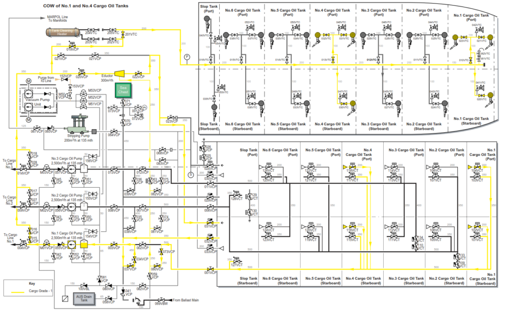
In this case example the intention is to discharge the group 1 tanks with COW of No.1 and No.4 COT whilst maintaining a two valve separation and no pipeline admixture.
a) Initially all cargo valves should be shut. The engineering department should prepare the IG system, initilise the O2 analyser and steam blow the boiler uptake valves, starting and stopping of the IG plant is conducted from the CCR. The engine room staff will also prepare the cargo oil pump turbines and auxiliary systems in order to make the cargo oil pump(s) ready for operation. Set up the cargo system and tanks ready to commence discharge of cargo. The intention is to discharge the starboard slop tank with No.1 COP and line.
| Position | Description | Valve |
| Open | Deck isolating valve and start IG system | 902VIG |
| Open | No.1 intermediate and bulkhead master valves | 001VCP 002VCP |
| Open | No.1 COP suction valve | 003VCP |
| Crack Open | Starboard slop tank suction valve | 127VCT |
b) Prime the No.1 bottom line and No.1 COPT separator. If using the AUS system gas extration valve to remove the atmosphere inside the pipline and separator, ensure the line up to the vacuum pumps is not also primed due to the head on the cargo tank. After the separator is fully primed the slop tank suction valve can be fully opened.
| Position | Description | Valve |
| Open | No.1 COP discharge valve to top line | M01VCP |
| Open | No.1 line top line block valve | 004VCP |
c) When the shore terminal confirm they are ready to receive cargo, open the manifold valves the lines are connected to, then start No.1 COP.
| Position | Description | Valve |
| Open | Manifold valves that the discharge valves are connected to | 202VCD if port side 201VCD if starboard side |
d) Commence the discharge at minimum speed, carrying out all safety and integrity checks after No.1 COP is started, then debottom all group 1 tanks by at least 1m to remove any wet crude.
| Position | Description | Valve |
| Open | No.1 COT suction valves | 101VCT 103VCT |
| Close | Starboard slop tank suction valve | 127VCT |
| Open | No.4 COT suction valves | 115VCT 117VCT |
| Close | No.1 COT suction valves | 101VCT 103VCT |
| Open | Starboard slop tank suction valve | 127VCT |
| Close | No.4 COT suction valves | 115VCT 117VCT |
e) Once the system has been proved, and with the shore installation’s agreement, increase the pump speed until the maximum permitted back pressure or flow rate is achieved.
e) As the starboard slop tank approaches the ullage for draining, start the automatic stripping system. On completion of draining the starboard slop tank, open No.1 COT.
| Position | Description | Valve |
| Close | Starboard slop tank suction valve | 127VCT |
| Open | No.1 COT suction valves | 101VCT 103VCT |
f) Refill the starboard slop tank with clean cargo to approximately 50% ullage, sufficient to cover the eductor discharge into the tank. Slowly open the slop tank main suction valve and recharge with fresh crude from No.1 COT.
| Position | Description | Valve |
| Open | Slop tank main suction valve | 127VCT |
g) On completion of recharging, shut the slop tank main suction valve and increase No.1 COP to maximum rpm. If sufficient ullage has not been attained in the slop tank, additional crude can be transferred to the starboard slop tank via No.1 COP discharge valves through the eductor.
| Position | Description | Valve |
| Close | Starboard slop tank main suction valve | 127VCT |
h) When No.1 COTs reach the top wash ullage, set up No.1 COP to supply crude from No.4 COT via the COW line to the fixed tank cleaning machines. If pressure cannot be maintained at 0.8MPa whilst washing two tanks then wash one tank at a time. When the top COW is completed return No.1 COP to discharging No.1 COT.
| Position | Description | Valve |
| Open | No.1 COP valves to the COW line | 015VCP 016VCP |
| Open | Pump room COW line isolating valves to tank cleaning machines | 019VCP 201VTC |
| Open | No.1 COT tank fixed tank washing machine valves | 010VTC 020VTC 021VTC 022VTC |
| Position | Description | Valve |
| Close | No.1 COT main suction valves | 101VCT 103VCT |
| Open | No.4 COT main suction valves | 115VCT 117VCT |
| Open | No.1 COT suction valves | 101VCT 103VCT |
| Close | No.4 COT main suction valves | 115VCT 117VCT |
i) When No.1 COTs reach the draining level, start the automatic draining system, open No.1 COT stripping suction valves and drain both tanks. On completion of draining change over to No.4 COT.
| Position | Description | Valve |
| Close | No.1 COP valves to the COW line | 015VCP 016VCP |
| Close | Pump room COW line isolating valves to tank cleaning machines | 019VCP 201VTC |
| Close | No.1 COT tank fixed tank washing machine valves | 010VTC 020VTC 021VTC 022VTC |
| Open | No.1 COT stripping suction valves | 102VCT 104VCT |
| Close | No.1 COT main suction valves | 101VCT 103VCT |
| Open | No.4 COT main suction valves | 115VCT 117VCT |
| Close | No.1 COT stripping suction valves | 102VCT 104VCT |
j) When No.4 COTs reach the draining level, set up the automatic draining system and drain both tanks. Now set up the No.1 COP to re-cycle on the starboard slop tank using the eductor to drain the COT.
| Position | Description | Valve |
| Open | Eductor discharge to starboard slop tank | 020VCP 022VCP 031VCP |
| Open | No.1 COP discharge to the COW line | 015VCP 016VCP |
| Open | Pump room COW line isolating valves to tank cleaning machines | 019VCP 201VTC |
| Position | Description | Valve |
| Open | No.1 and No.4 COTs fixed tank washing machine valves | 010VTC 020VTC 021VTC 022VTC 013VTC 030VTC 031VTC 032VTC |
| Close | No.1 COP isolating valve to top line | 004VCP |
| Open | Eductor suction valves to No.1 bottom line | 063VCP 060VCP 073VCP |
| Open | No.1 COP suction to port slop tank | 034VCP 037VDP 032VCP |
| Close | No.1 bottom line intermediate block valve | 002VCP |
| Close | No.4 COT main suction valves | 115VCT 117VCT |
| Close | No.1 manifold port or starboard that the shore hose is connected to. | 202VCD or 201VCD |
| Open | No.1 COT stripping suction valves | 102VCT 104VCT |
| Open | No.4 COT stripping suction valve | 116VCT 118VCT |
| Close | No.1 COT stripping suction valves | 102VCT 104VCT |
k) On completion of COW, discharge the starboard slop tank ashore, draining the tank with the automatic draining system.
| Position | Description | Valve |
| Close | Eductor discharge to starboard slop tank | 020VCP 022VCP 031VCP |
| Close | No.1 COP discharge to the COW line | 015VCP 016VCP |
| Close | Pump room COW line isolating valves to tank cleaning machines | 019VCP 201VTC |
| Position | Description | Valve |
| Close | No.1 and No.4 COTs fixed tank washing machine valves | 010VTC 020VTC 021VTC 022VTC 013VTC 030VTC 031VTC 032VTC |
| Open | No.1 COP isolating valve to top line | 004VCP |
| Close | Eductor suction valves to No.1 bottom line | 063VCP 060VCP 073VCP |
| Close | No.1 COP suction to port slop tank | 034VCP 037VDP 032VCP |
| Open | No.1 bottom line intermediate block valve | 002VCP |
| Open | Starboard slop tank suction | 127VCT |
| Close | No.4 COT stripping suction valve | 116VCT 118VCT |
l) When draining is completed stop No.1 COP, shut the manifold valve, port or starboard, that the shore hose is connected to and drain lines as explained before in blog.
| Position | Description | Valve |
| Close | No.1 Manifold valves | 202VCD or 201VCD |
| Close | Starboard slop tank suction valve | 127VCT |
| Close | No.1 COP top line isolating valve | 004VCP |
| Close | No.1 top line block valve | 263VCD |
| Close | No.1 COP suction valve | 003VCP |
| Close | No.1 COP discharge valve | M01VCP |
| Close | No.1 bottom line intermediate block valve | 002VCP |
| Close | No.1 bottom line bulkhead master valve | 001VCP |
m) On completion of line draining close all valves and agree ship/shore figures.
Segregated ballast loading should be started as in the chief officer’s discharging plan, consistent with maintaining the trim and stress within acceptable limits.