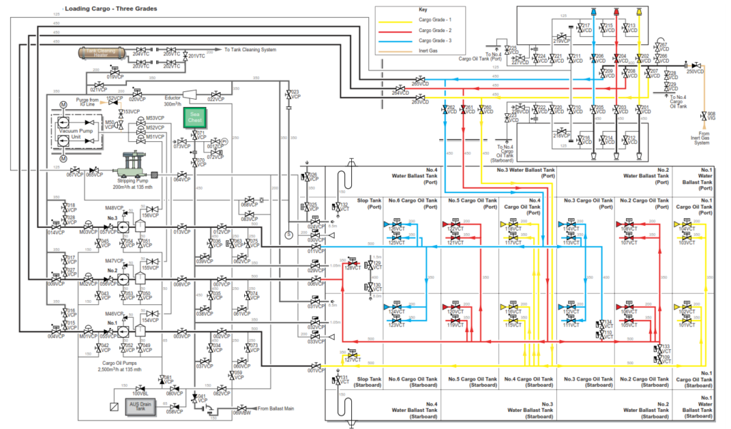
Below loading is explained basis my present vessel. See the diagram for better understanding.
The cargo oil tanks are divided into three segregations or groups which can be used either individually or combined to permit the loading of the nominated quantities.
Group 1 consists of No.1, No.4 COTs and the starboard slop tank Group 2 consists of No.2, No.5 COTs and the port slop tank Group 3 consists of No.3 and No.6 COTs
Prior to arrival at the loading port, a number of communications take place between the loading terminal and the vessel. These are based on the ISGOTT guide checklists.
Particular attention should be given to:
• Emergency shutdown procedures
• Closed loading techniques
• Topping off techniques
• Oil spill response procedures
• The manifold area and the mooring systems
WARNING:The greatest free surface effect is when the ballast water level has cleared the trunkway (3m sounding) in the side tanks and is solely in the double bottom area. If, at the same time, the cargo level is low, the combined effect of a relatively small displacement and the free surface effect in the cargo, ballast tanks could result in a negative GM. This may lead to the vessel developing an angle of loll.
LOADING A SINGLE GRADE CARGO
Prior to arrival at the load port a number of checks and tests must be carried out to verify the correct operation of the cargo hydraulic and monitoring systems.
The vapour recovery/inert gas line is fitted with a PV breaker and vent mast riser. Check that the PV breaker sight glass indicates the correct level of fluid and also that the vent mast riser valve operates correctly.
Each cargo tank is fitted with a combined pressure vacuum valve. The test levers on both the pressure and vacuum valves must be operated to confirm that the valves are free to operate on their seats before loading or unloading.
After planning the stability, taking into consideration the maximum permissible draught, bunkers, water and extras, the loading of a single grade homogeneous cargo is relatively straightforward.
Note: Loading operations are carried out via the cargo control room console and mimic panel plus a number of remote manual valves on deck. All remote hydraulic valves operated from the mimic panel use either the open/close pushbuttons, or the proportional open/close valves are operated using the control switches. The hydraulic remote/manual valves on deck are contained inside the respective solenoid boxes and have control levers to operate the valves.
All manually operated valves only have status indication on the mimic panel.
a) Ensure the IG isolating valve for each cargo tank is in the open position, the spade blanks are rotated to OPEN and each tank hatch is securely closed.
b) Check that the IG deck isolating valve, 902VIG is closed.
When preparing the system to load cargo, it is important to ensure that all valves are in the closed position prior to commencing the setting of the cargo lines.
c) Ensure that all overboard valves are in the closed position and sealed and that the spectacle pieces are swung and secured in the closed position.
d) Ensure that all unused manifold valves are blanked and shut.
e) Manually open vent mast riser valve 909VIG to the required setting if VEC is not to be used to control the IG pressure in the tanks. Initially, the setting of the mast riser valve can be adjusted to allow the IG pressure to fall momentarily to the extra low pressure value in order to test the COPT trips.
f) Open the deck drop loading valves, the cargo group isolation valves and the required tank suction valves.
g) Open the manifold valves to which the loading arms are connected.
h) Start loading cargo at the agreed slow rate into one tank. When cargo is confirmed as coming into the selected tank, other tank valves may be opened as required and the loading rate increased to the agreed figure. Manually adjust the vent mast riser valve accordingly to maintain the IG pressure inside the tanks.
i) Create an appropriate stagger for controlled topping off and reduce the loading rate in ample time.
j) Ensure the ballast operations are completed in advance of the final topping off.
The trimming tanks are the slack COTs resulting from trim, draught or nominated cargo restrictions. These are normally No.1 and No.6 COTs. Trimming tanks are filled to pre-planned ullages and then shut. They are brought to their final ullage towards the end of loading, at a reduced loading rate.
It is always advisable to complete loading in a slack tank in order to reduce the risk of a carryover of cargo to the inert gas main. Slack tanks should be kept to a minimum in order to reduce the free surface effect.
Deballasting is to be started in accordance with the chief officer’s loading plan which is generally after bulk loading is under way.
Initially all valves are shut and the position of all valves are indicated on the cargo control console mimic panel.
| Position | Description | Valve |
| Close | Deck IG isolating valve | 902VIG |
| Open | Manifold valve that the VEC recovery arm is connected to or Mast riser if no VEC | 906VIG 907VIG 904VIG 905VIG 909VIG |
| Open | No.1, 2 and 3 loading drop valves | 260VCG 261VCG 262VCG |
| Open | Segregation valves line 1 to line 2 | 109VCT 133VCT |
| Open | Segregation valves line 2 to line 3 | 110VCT 134VCT |
| Open | No.3 port wing tank | 113VCT |
| Open | The manifold valves that loading arms are connected to (port side) (starboard side) | 202VCD 204VCD 206VCD 201VCD 203VCD 205VCD |
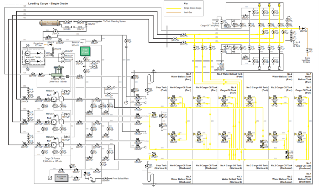
k) Commence loading at the agreed slow rate until the initial safety and integrity checks are completed and cargo is being received into the first cargo tank, then open all tanks in the loading plan and slowly increase to the agreed full loading rate. Control the IG pressure on the IG main by manually controlling the position of the vent mast riser valve 909VIG in order to balance the IG being displaced with the cargo
| Position | Description | Valve |
| Open | No.1, 3, 5 COTs and both slop tanks | 101VCT 102VCT 103VCT 104VCT 111VCT 112VCT 114VCT 119VCT 120VCT 121VCT 122VCT 128VCT 127VCT |
l) Stagger the tanks and reduce the loading rate in preparation for topping off tanks.
m) Top off the first sets of COTs.
When topping off the first set of COTs, commence loading into the remaining empty tanks to reduce the loading rate into the first group of tanks.
| Position | Description | Valve |
| Open | No.2, 4, 6 COTs | 105VCT 106VCT 107VCT 108VCT 115VCT 116VCT 117VCT 118VCT 123VCT 124VCT 125VCT 126VCT |
CAUTION: Ensure that some of the second group of tanks are open before completion of the first group in order to avoid a pressure surge in the lines during changeover
| Position | Description | Valve |
| Close | No.1, 3, 5 COTs and both slop tanks | 101VCT 102VCT 103VCT 104VCT 111VCT 112VCT 114VCT 119VCT 120VCT 121VCT 122VCT 128VCT 127VCT |
n) Shut the required finishing and trimming tanks at a suitable ullage, adjusting the loading rate as required. Manually adjust the position of the vent mast riser valve accordingly as the loading rate is reduced, consistent with maintaining the correct IG main line pressure.
o) Create an appropriate stagger for controlled topping off, reduce the loading rate in sufficient time.
p) On completion of cargo loading, drain all the loading tanks into a slack tank and close all valves. q) Agree ship/shore figures and disconnect the loading arms.
LOADING A TWO OR THREE GRADE CARGO
Prior to arrival at the load port checks and tests must be carried out to verify the correct operation of the cargo hydraulic and monitoring systems.
The vapour recovery/inert gas line is fitted with a PV breaker and vent mast riser. Check that the PV breaker sight glass indicates the correct level of fluid also that the vent mast riser valve operates correctly.
Each cargo tank is fitted with a combined pressure vacuum valve. The test levers on both the pressure and vacuum valves must be operated to confirm that the valves are free to operate on their seats before loading or unloading.
After planning the stability, taking into consideration maximum permissible draught, bunkers, water and extras, the procedure to load a multigrade crude oil cargo is very similar to that for a single grade, the worst case scenario being that three grades are to be loaded and discharged whilst maintaining a two valve separation.
The following assumes that the vapours from each grade are compatible with the other grades being loaded. If this is not the case, only grades with compatible vapours can be loaded concurrently when the VEC is in use.
a) Ensure the IG isolating valve for each cargo tank is in the open position, the spade blanks are rotated to OPEN and each tank hatch is securely closed.
b) Check that the IG deck isolating valve, 902VIG is closed.
When preparing the system to load cargo, it is important to ensure that all valves are in the closed position prior to setting the cargo lines.
c) Set the cargo lines ensuring that the required valve segregation is observed. Double check the line settings prior to commencing cargo operations.
d) Ensure that all overboard valves are closed and sealed.
e) Ensure that all unused manifold valves are shut and blanked.
f) Open the required tank suction valves in each of the groups.
g) Open the manifold valves to which the loading arms are connected.
h) Commence loading, one grade at a time at the agreed reduced rate. Once satisfied that the cargo is flowing only into the selected tanks, loading of the second and third grades can be commenced in the same manner.
i) Create an appropriate stagger for controlled topping off, reduce the loading rates in ample time.
j) Ensure the ballast operation is completed in advance of the final topping off.
k) On completion of loading, drain all the loading lines into slack tanks and close all valves on the cargo system.
The trimming tanks are the slack COTs resulting from trim, draught or nominated cargo restrictions. These are usually COTs No.1 and No.6, or body tanks such as COTs No.3.
Trimming tanks are filled to a pre-planned ullage and then shut. They are brought to their final ullage towards the end of loading at a reduced loading rate.
It is always advisable to complete loading in a slack tank in order to reduce the risk of a carry-over of cargo to the inert gas main. Slack tanks should be kept to a minimum in order to reduce the free surface effect.
Deballasting is to be started shortly after bulk loading is under way. Segregated ballast should be discharged as required to assist in maintaining a reasonable trim.
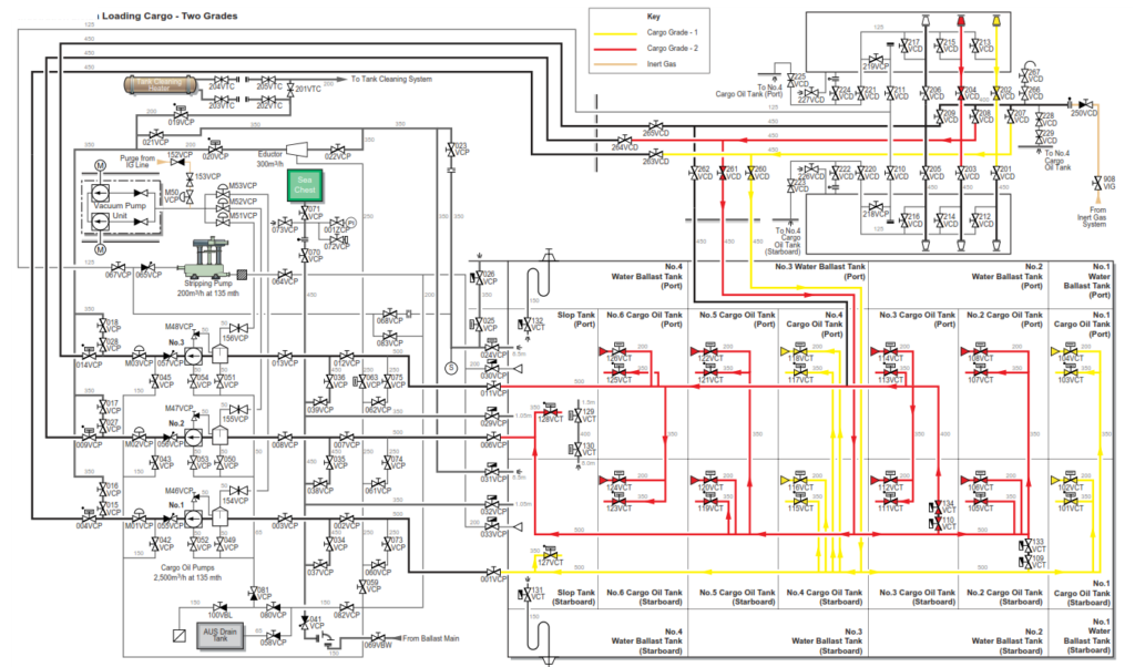
Loading a Two Grade Cargo
Assuming that a two valve separation is required to be maintained between the grades it is necessary to load using a combination of the loading groups. This could be group one for the 1st grade and groups two and three for the 2nd. Any combination of the groups can be used subject to the quantities required and the stress/stability requirements.
Assuming that two grades are being loaded. Initially all valves are shut.
| Position | Description | Valve |
| Close | Deck main IG isolating valve | 902VIG |
| Open | Manifold valve that the VEC recovery is connected to: or The mast riser if no VEC | 906VIG 907VIG 904VIG 905VIG 909VIG |
| Open | No.1 and No.2 drop valves | 260VCD 261VCD |
| Open | No.2 and No.3 bottom line crossover valves | 110VCT 134VCT |
Grade One (Group One)
| Position | Description | Valve |
| Open | Group 1 cargo oil tank valves: No.1, 4 COT and starboard slop tank | 101VCT 102VCT 103VCT 104VCT 115VCT 116VCT 117VCT 118VCT 127VCT |
| Open | No.1 manifold valve port or starboard | 202VCD or 201VCD |
Grade Two (Groups Two and Three)
| Position | Description | Valve |
| Open | Group 2 and 3 cargo oil tank valves: No.2, 3, 5, 6 COT and port slop tank | 105VCT 106VCT 107VCT 108VCT 111VCT 112VCT 113VCT 114VCT 119VCT 120VCT 121VCT 122VCT 123VCT 124VCT 125VCT 126VCT 128VCT |
| Open | No.2 manifold valve port or starboard | 204VCD or 203VCD |
a) Commence loading grade 1 at the agreed slow rate until the initial safety and integrity checks are completed, including manifold and overside checks, then increase to the agreed full loading rate. Manually adjust the mast riser valve 909VIG to balance the IG main pressure consistent with the flow rate and the IG being displaced by the cargo oil.
b) Commence loading grade 2 in the same manner as for grade 1.
c) Stagger the tanks and reduce the loading rates to comply with trim and stress requirements.
d) Prior to topping off close the stripping suction on the COTs leaving only the main suction valve open.
Note: When the stripping suction on a COT is shut leaving only the main suction valve open, the loading rate should be reduced by the maximum rate for the tank .
e) Top off each group in turn. It is likely, due to the loading rates for each group differing, that the grades will not finish in the same order that they started. Monitor the IG main pressure, manually adjusting the mast riser valve 909VIG accordingly.
f) Drain all top lines and loading arms to a slack tank in each group.
g) Close all cargo valves.
h) Agree ship/shore figures and disconnect the loading arms.
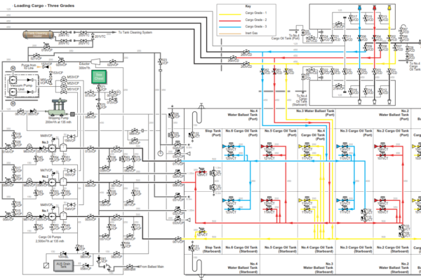
Loading a Three Grade Cargo
Assuming that three grades are being loaded. Initially all valves are shut:
| Position | Description | Valve |
| Close | Deck main IG isolating valves | 902VIG |
| Open | Manifold valve that the VEC recovery is connected to: or Mast riser if no VEC | 906VIG 907VIG 904VIG 905VIG 909VIG |
| Open | No.1. 2 and No.3 drop valves | 260VCD 261VCD 262VCD |
Grade One (No.1 Top and Bottom Line)
| Position | Description | Valve |
| Open | Grade 1 cargo oil tank valves: No.1, 4 COT and starboard slop tank | 101VCT 102VCT 103VCT 104VCT 115VCT 116VCT 117VCT 118VCT 127VCT |
| Open | No.1 manifold valve port or starboard | 202VCD or 201VCD |
Grade Two (No.2 Top and Bottom Line
| Position | Description | Valve |
| Open | Grade 2 cargo oil tank valves: No.2, 5 COT and port slop tank | 105VCT 106VCT 107VCT 108VCT 119VCT 120VCT 121VCT 122VCT 128VCT |
| Open | No.2 manifold valve port or starboard | 204VCD or 203VCD |
Grade Three (No.3 Top and Bottom Line
| Position | Description | Valve |
| Open | Grade 3 cargo oil tank valves: No.3, 6 COT | 111VCT 112VCT 113VCT 114VCT 123VCT 124VCT 125VCT 126VCT |
| Open | No.3 manifold valve port or starboard | 205VCD or 206VCD |
a) Commence loading group 1 at an agreed slow rate until the initial safety and integrity checks are completed, including manifold and overside checks, then increase to the agreed full loading rate. Manually adjust the mast riser valve 909VIG to balance the IG main pressure consistent with the flow rate and the IG being displaced by the cargo oil.
b) Commence loading grade 2 followed by grade 3 in the same manner as for grade 1.
c) Stagger the tanks and reduce the loading rates to comply with trim and stress requirements.
d) Prior to topping off close the stripping suction on the COTs leaving only the main suction valve open.
Note: When the stripping suction on a COT is shut leaving only the main suction valve open, the loading rate should be reduced by the maximum rate for the tank.
e) Top off each group in turn. It is likely, due to the loading rates for each group differing, that the grades will not finish in the same order that they started. Monitor the IG main pressure, manually adjusting the mast riser valve 909VIG accordingly.
f) Drain all top lines and loading arms to a slack tank in each group.
g) Close all cargo valves.
h) Agree ship/shore figures and disconnect the loading arms.