System explained basis my present vessel
Cargo oil tanks are crude oil washed to comply with both legislation (contingency ballast requirements) and charterer’s requirements in order to achieve maximum out-turn. This would usually be No.4 COT port and starboard (nominated heavy weather ballast tanks) and one quarter of the remainder. However, no tank requires to be washed more than once in four months, with the exception of ballast requirements.
A programme for the regular crude washing of cargo tanks is to be maintained. Crude oil washing permits the removal of oil fractions adhering to or deposited on the tank surfaces. These deposits, which would normally remain on board after discharge, are then discharged with the cargo. As a consequence, the need to water wash to remove residues is virtually eliminated. Water rinsing will be necessary if the tank is to be used for clean ballast.
A typical crude oil washing program is as follows:
1st voyage
No.1 and 4 COTs and one slop tank
2nd voyage
No.2 and 4 COTs and one slop tank
3rd voyage
No.3 and 4 COTs
4th voyage
No.4 and 5 COTs
Leakage of crude oil from the COW system is a potential fire and pollution hazard. Before use, the system should be pressure tested to working pressure and any leaks made good. Reference should be made to the vessel’s approved Crude Oil Washing Manual.
CAUTION :The cargo stripping pump is a positive displacement pump and therefore must never be used to pressure test the COW line.
During COW operations the system must be kept under continuous observation and the tanks fully inerted. Crude oil washing must be stopped immediately if there are any signs of leakage or a malfunction is detected, or there is a failure of the IG system.
Before commencing COW it is necessary to debottom all COTs, including the slop tanks; this will remove any water that may have settled during transit. Debottoming will considerably reduce the risk of any static charges that may be created during washing.
Where any tank has been used for load on top and it is intended to use them for COW, they should be discharged in their entirety and then recharged.
If the slop tanks are to be used for COW, it is, subject to grade segregation, usually advisable to empty the slop tanks and recharge them with fresh dry crude prior to commencement. The levels to which the slop tanks are recharged are arbitrary, but sufficient ullage, (approximately 11m if using one tank and 8m if using both tanks) is required in the clean slop tank to allow for the cargo pump to maintain suction and the balance line to remain covered.
In the slop tanks the balance line outlet is at approximately 10m above the tank floor level in the starboard clean slop tank, and the inlet 1.5m above the tank bottom in the port dirty slop tank.
This method of COW allows for greater ullage and easier monitoring of the crude oil returns, but it is quite feasible to utilise a single slop tank for the operation, reducing the level occasionally to maintain a safe ullage.
During COW operations one of the major factors in ensuring the tank top and bulkheads are cleaned of residues, sludge etc., is the level of solvency in the COW liquid. As the period of COWing continues this level of solvency will diminish if only one source is being used. As a number of tanks required to be COW’d as per the charterers instructions (full bottom wash of all tanks and at least two COT top washes) may well be above the minimum MARPOL requirement, it may well be necessary to either discharge the slop tanks and then recharge them after a number of tanks have been completed, or conduct half of the COW with one slop tank, then the other half with the second slop tank. During the transit period to the discharge port it is advisable when hand dipping the tanks to gauge the degree of sediment, sludge etc at the tank bottom. The degree of sediment present can influence the amount of time it will take to conduct a COW of the individual tanks and the level of ROB at the finish of discharge. Therefore when formulating the discharge plan, it may be necessary to take this information into account when setting the stagger for the tanks.
COTs are crude oil washed during discharge by pumping dry crude, at a back pressure of about 0.8MPa, bled from the discharge of one of the cargo oil pumps via the tank cleaning line to the tank cleaning machines.
The eductor is driven by the same cargo oil pump that is being used to drive the COW machines. It is also used to drain the oil fractions from the cargo tank bottom to a slop tank. Good draining is essential during COW operations. The stripping suctions are in wells and a slight port list during draining would be beneficial.
WATER WASH – (COLD OR HOT)
Cold washing (water rinsing) of COTs is required for the following purposes:
• Prior to the ballasting of COTs which have previously been crude oil washed, where the ballast is to be treated as clean ballast.
• Prior to refit, or the inspection of COTs that have previously been crude oil washed.
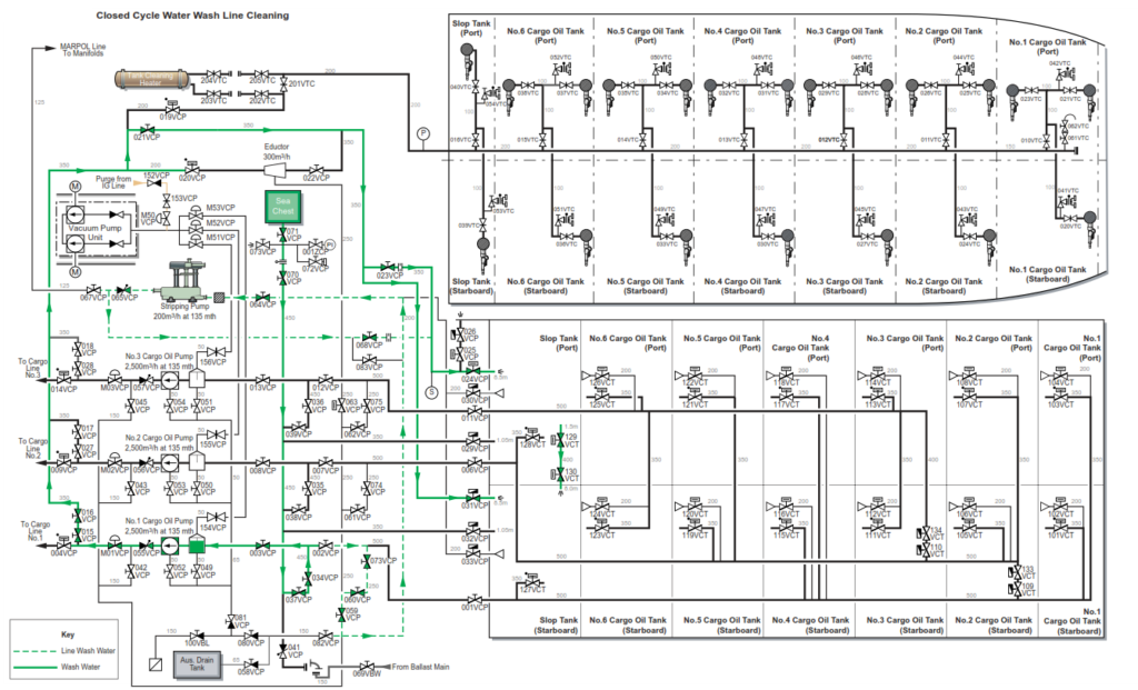
Procedure for the Operation of the Tank Cleaning System
When preparing the system for tank cleaning, it is important to ensure that all valves are in the closed position prior to setting the lines. A line wash must be carried out before the operation can commence.
a) Ensure the COT(s) to be washed is inerted and that the oxygen content is less than 8%.
b) Drain all crude oil from the tank cleaning main to the slop tank by opening a slop tank cleaning machine and one of the cleaning machines at the forward end of the tank cleaning main. Ensure these valves are closed prior to commencement of tank cleaning.
c) As it is necessary to charge both slop tanks with clean sea water, the spectacle flange between valves 070VCP and 071VCP must be turned into the OPEN position. When the spectacle flange has been turned, keeping both the main sea valves shut, line up the stripping pump from the sea chest to the port slop tank.
d) Open the slop tank balance line.
e) Start the stripping pump in order to create a vacuum at the inboard side of the sea suction.
f) Open the inboard sea valve, check for a vacuum, then open the outboard sea valve, sea water will now be drawn through the sea water chest and discharged to the port slop tank.
g) On the COP to be used for tank washing, a basic line wash is necessary. Line up the COP to take suction from the sea and discharge to the port slop tank via the eductor bypass line.
h) Start the COP on tank cleaning duty.
i) When the COP has suction, stop the stripping pump and shut it down.
j) Charge the slop tanks to a level that is higher than the balance line outlet in the starboard slop tank, the height of which is located at approximately 50% of the tank volume.
k) Change over the COP from the sea suction to the starboard slop tank suction, discharging to the port slop tank through the eductor. The eductor is to be used to drain the tank being washed.
l) Open the stripping suctions on the cargo oil tank to be washed. m) Open the required tank cleaning machines.
Complete at least one bottom wash, one full cycle and one more bottom wash. The patterns given are for a general wash, the actual duration required will be found with experience. The stripping suction valves in the COTs are in stripping wells, therefore the vessel should be given a slight port list during draining.
n) Monitor the slop tank ullages and total quantities carefully.
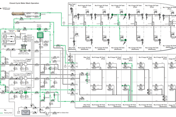
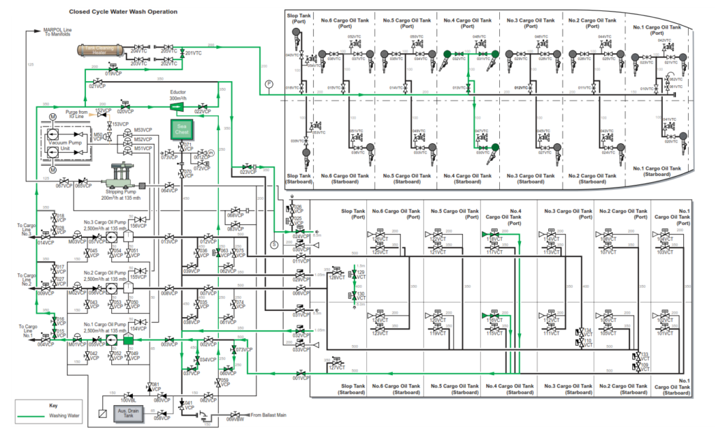
The above method of water wash is entitled ‘Closed Cycle’, and is considered to be the most manageable and controlled method of tank washing.
Closed Cycle Washing
Assuming No.4 COTs are being washed for inspection using No.1 COP as the tank cleaning pump and that the sea chest spectacle flange between valves
070VCP and 071VCP has been turned into the open position.
a) Commence with all valves closed.
| Position | Description | Valve |
| Open | Stripping pump suction valve to sea chest | 064VCP 059VCP 060VCP 073VCP 002VCP 034VCP 037VCP |
| Open | Stripping pump discharge valves to port slop tank | 065VCP 068VCP 024VCP |
| Open | Open the slop tanks balance line | 129VCT 130VCT |
b) Start the stripping pump. When a vacuum shows on the suction side of the pump.
| Position | Description | Valve |
| Open | Intermediate sea valve | 070VCP |
c) When a vacuum shows at the sea chest.
| Position | Description | Valve |
| Open | Main sea valve | 071VCP |
d) Monitor and verify there is a positive flow to the port slop tank, then set up No. 1 COP to prime the slop tanks.
| Position | Description | Valve |
| Open | No.1 COP discharge line to both slop tanks | 015VCP 016VCP 023VCP 024VCP 021VCP 031VCP |
| Open | No.1 COP suction valve | 003VCP |
e) Start the COPT, when at minimum speed open the pneumatic discharge valve.
| Position | Description | Valve |
| Open | No.1 COP discharge valve | M01VCP |
f) When the rpm is steady and flow is established into the slop tanks, stop the stripping pump and close the stripping pump suction valves to the sea chest and discharge to port slop.
| Position | Description | Valve |
| Close | Stripping pump suction valves to sea chest | 002VCP 073VCP 060VCP 059VCP 064VCP |
| Close | Stripping pump discharge valves to port slop tank | 065VCP 068VCP |
g) Fill the slop tanks until there is sufficient water in each to cover the levelling line outlet in the starboard slop tank.
h) Change the cargo oil pump on tank cleaning duty to draw from the starboard slop tank cleaning suction and discharge back to the port slop tank via the eductor.
| Position | Description | Valve |
| Open | Starboard slop tank, tank cleaning suction valve | 032VCP |
| Open | Eductor inlet valve and outlet valves | 020VCP 022VCP |
| Open | Eductor suction valve | 063VCP |
| Close | Eductor bypass valve | 021VCP |
| Open | Eductor discharge valve to port slop tank | 023VCP 024VCP |
| Close | Inboard and ship side sea valves | 070VCP 071VCP |
i) The vessel is now ready to carry out tank cleaning, using cold wash water from the slop tanks or, if hot water is required, the tank cleaning heater and slop tank heating coils will be required.
j) Open the tank cleaning line isolating valve 019VCP and 201VTC.
k) Open the eductor suction into No.1 line and the stripping suction valves for No.4 COT.
| Position | Description | Valve |
| Open | Eductor suction valves to No.1 line | 060VCP 073VCP |
| Open | No.4 COT stripping suction valves | 116VCT 118VCT |
| Open | No.4 line bulkhead valve | 001VCP |
l) Open the individual tank cleaning machine isolating valves on No.4 COT.
| Position | Description | Valve |
| Open | Tank cleaning machines on No.4 COT | 013VTC 030VTC 031VTC 032VTC |
No.4 cargo oil tanks are now being water washed on a closed cycle. Maintain the required pressure for the tank cleaning machines and eductor drive by regulating the tank cleaning pump discharge valve or the speed of the pump.
As an alternative, any of the cargo pumps could be used to supply the drive fluid to eductor and tank cleaning machines.
Hot Water Wash
A tank cleaning heater is fitted in the top of the pump room capable of heating sea water from 20°C to 80°C with a throughput of 160m3/h. In addition heating coils are fitted in both slop tanks. Eight sets of coils are fitted to the port slop tank and are capable of heating the sea water contents from 15°C to 66°C over a period of 24 hours with a sea water temperature of 5°C and air temperature of 2°C. The starboard slop tank has two coils fitted
The closed cycle method of cleaning as described above, would be required for hot washing.
Slop Tank Heating Coils
Both slop tanks are fitted with heating coils in multi-tiers with specification as follows:
| Description | Port Slop Tank | Stbd Slop Tank |
| Maximum steam consumption (kg/h) | 10835 | 650 |
| Heating coil surface area (m3) | 119 | 23 |
| Heating coil ratio | 0.0505 | 0.0098 |
| Heating coil length (m) | 513.6 | 92.1 |
| Loop | 8 | 2 |
| Length per downcomer and exhaust combined (m) | 48 | 47 |
| Volume 50% (m3) | 1185.0 | 1185 |
| Volume 98% (m3) | 2324 | 2324 |
The slop tank heating coils steam supply is fed from the engine room 0.6MPa system.
Each tank is fitted with a steam and a condensate header. There are drain valves on both headers which are used to test the quality of the condensate returns.
The condensate from the slop tank heating coils is led back to the feed filter tank through the atmospheric condenser and an inspection tank in the engine room.
The normal method of testing the coils is simply to crack steam on to the system and test the quality of the condensate returns.
WARNING :Water hammer in steam lines can be a problem resulting in possible damage to the pipe system and even steam line failure resulting in scalding of personnel. It is essential that all steam lines are drained of condensate and that steam is supplied to cold lines gradually with line drain valves open. This allows the steam line to warm through and for the condensate to drain.
Procedure for the Operation of the Slop Tank Heating System
All valves and drains are closed.
a) Open the main condensate return valve to the engine room, directing the slop tanks heating condensate to the atmospheric condenser.
b) Open the deck steam master valve to the slop tank heating coils.
c) Open the steam header drain valve, then crack open the header steam isolating valve. When the drains run clear close the drain valve.
d) Open the condensate drain valve on the condensate header fully on each coil.
e) Open the steam inlets to each coil and warm through each coil slowly, until the steam header isolating valve is fully open.
f) Check the drain cocks on each coil for any contamination.
g) When all the drains have run clear, open the condensate header return isolating valve.
h) Open the condensate outlet valves from each coil then close the drain valves.
If traces of oil emerge at the condensate drains valves, inform the chief officer and shut off the steam supply to that coil.
i) Monitor the observation tank for contamination.
Shutting Down the System
a) Shut off all individual tank steam and condensate valves.
b) Open drain valves to prevent a vacuum forming which could draw in oil through any pipe defects.
c) Close drain valves when the coils have reached ambient temperature, this in order to prevent any ingress of sea water during heavy weather.
d) Close the main supply and return valves.
Contamination
If contamination should occur at the observation tank proceed as follows:
a) Check the condensate drains on each slop tank and locate the defective coil.
b) Isolate the defective heating coil and insert blanks in the steam inlet and condensate outlet lines.
c) Proceed to heat the tank using the other coils.
Testing the Coils
The modern materials and the continuous welded construction used in the heating coils tend to offer reliable service. Routine testing by checking the condensate outlet when putting the system into use will normally suffice. However, pin holes can develop at welds and loose pipe brackets can cause fretting.
If contamination occurs, test the defective coils at the next possible opportunity. This is done by supplying steam to the coil with the outlet valve closed, making a tank entry and locating the leakage.
A permanent repair will, in most cases, require welding. This would be carried out during refit. A near permanent repair can be carried out by cutting the coil in way of the defect and inserting a Yorkshire coupling.