System explained basis my present vessel.
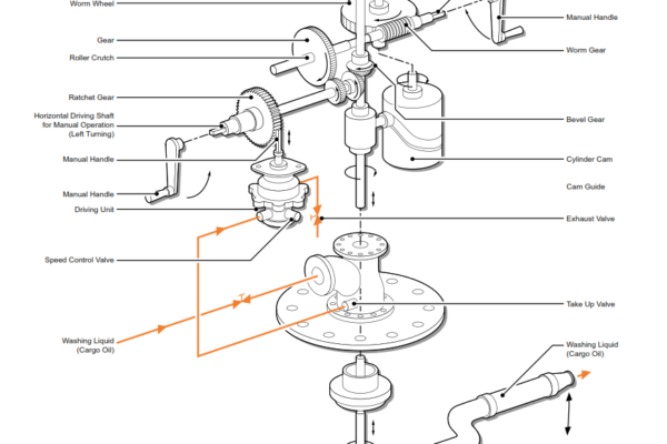
The deck mounted tank cleaning machines are turbine driven, fully programmable, single nozzle units. The nozzle performs a helical pattern by rotating in a horizontal plane, combined with a very slow vertical movement. The machine can rotate 360° in the horizontal plane and up to 135° in the vertical plane.
The revolutions per minute are increased or decreased using the speed control valve on the driving unit. The speed range for one horizontal pass ranges from a minimum of 60 seconds with the speed control dial fully wound in, to a maximum of 135 seconds with the speed control dial fully wound out. There is approximately 2.5 turns of the speed control dial between minimum and maximum speed.
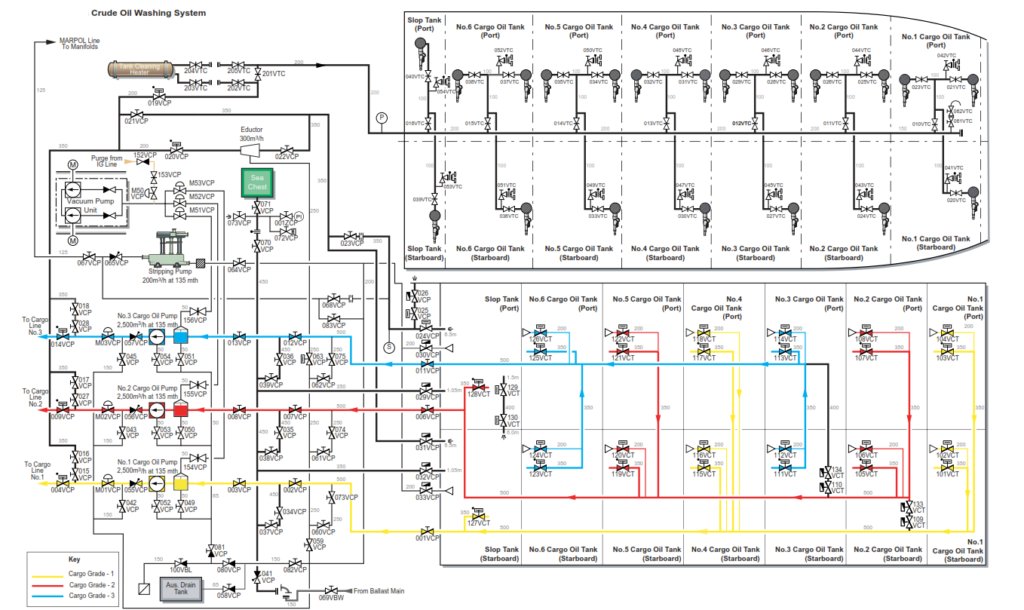
Tank Cleaning Machine Arrangement
The vertical pitch is preset and cannot be changed but varies with angular setting of the nozzle. Pitch is the angular difference between two points on the tank side, with the nozzle pointing in the same direction on successive rotations. Although the pitch setting cannot be changed, the actual pitch does vary, the pitch detail is given is the following section.
Washing Time Table
| One Horizontal Rotation Time of a Nozzle | |||||
| One Horizontal Rotation Set Time (s) | 60 | 90 | 120 | 135 | |
| Washing Limits Angle | 135° – 0° | 60 | 90 | 120 | 135 |
| 90° – 0° | 43 | 64 | 85 | 96 | |
| 60° – 0° | 30 | 45 | 60 | 68 | |
| 25° – 0° | 10 | 15 | 20 | 23 | |
| 135° – 90° | 17 | 26 | 35 | 39 | |
| 135° – 60° | 30 | 45 | 60 | 67 | |
| 135° – 25° | 50 | 75 | 100 | 112 | |
| 90° – 60° | 13 | 19 | 25 | 28 | |
| 90° – 25° | 33 | 49 | 65 | 73 | |
| 60° – 25° | 20 | 30 | 45 | 45 | |
Spot or manual washing can be carried out by closing the driving fluid intake valve then adjusting the direction of the nozzle and the vertical angle of the nozzle using the crank handle then opening and closing the washing fluid valve as required. On the top of the drive unit is a cover which protects the indicator spindle, this spindle is used by the operator to set the correct starting angle of the nozzle.
The indicator rotates during operation of the COW, a marker on to of the indicator can be used to gauge the time interval of each revolution, allowing the correct speed setting to be made accordingly. This marker is also used to give the operator the direction of the nozzle when conducting a spot wash.
The ship is provided with a separate 200mm COW/tank cleaning line, with branches to each tank washing machine. A main cargo pump is required to supply the driving fluid to the tank cleaning machines and stripping eductor when they are in use.
Final draining is carried out using the stripping eductor while the automatic stripping system fitted to each main cargo pump is used for initial draining during washing.
A tank cleaning heater is fitted in the top of the pump room capable of heating sea water from 20°C to 80°C with a through put of 160m3/h. In addition heating coils are fitted in both slop tanks. Eight sets of coils are fitted to the port slop tank and are capable of heating the sea water contents from 15°C to 66°C over a period of 24 hours. The starboard slop tank has two coils fitted.
The capacity of each cargo pump is adequate for supplying driving fluid to the eductor and tank cleaning machines for two cargo tanks. The suction capacity of the eductor is 125% of the output of all the COW tank cleaning machines when washing both a port and starboard cargo oil tank.
Washing Programme
| 130° to 70° for main cargo tanks, top cleaning at 60 seconds/ revolution | = 25 minutes |
| 130° to 40° for slop tanks, top cleaning at 75 seconds/revolution | = 50 minutes |
| 70° to 0° for main cargo tanks, bottom cleaning at 90 seconds/ revolution | = 51 minutes |
| 40° to 0° for slop tanks, bottom cleaning at 135 seconds/ revolution | = 42 minutes |
OPERATION AND MAINTENANCE OF THE COW MACHINES (ROUTINE MAINTENANCE IN OPERATION ONLY)
Before any tank cleaning operations are carried out the line must be inspected and tested to full working pressure, any faults or leaks must be rectified before the system is used.
CAUTION :The cargo stripping pump is a positive displacement pump and therefore must never be used to pressure test the COW line.
Operation of the Tank Cleaning Machines
a) Remove the vertical scale protective cover.
b) Using the manual hand crank, preset the nozzle to any desired starting angle. The perspex cover on the indicator spindle is graduated at the following values, 0°, 25°, 60°, 90°, 120° and 135°.
CAUTION: Before cranking the nozzle to a new position close the drive fluid intake valve.
c) When the machine starts to wash, the nozzle always goes down therefore set nozzle to the upper angle required.
d) To start the machine, open the wash fluid valve slowly in order to avoid any liquid shock.
e) Open the drive fluid drain valve and the drive fluid inlet valve.
f) On completion of tank cleaning, close the wash fluid valve and reset the machine to the rest position by cranking the nozzle to the bottom position, 0°.
g) Replace and lock the protective cover.
h) After about two minutes close both the drive fluid intake valve and the drive fluid drain valve.
Speed Adjustment
The speed of the unit can be regulated by opening and closing the speed control valve which is situated on the drive fluid intake line. The direction the nozzle is pointing in is shown by an indicator line on the head of the indicator spindle.
Pitch Adjustment
The vertical pitch is preset and varies with regard to the washing range as per the following table.
135° to 90° = 2.6°
90° to 60° = 2.4°
60° to 25° = 1.75°
25° to 0° = 2.5°
Spot Washing
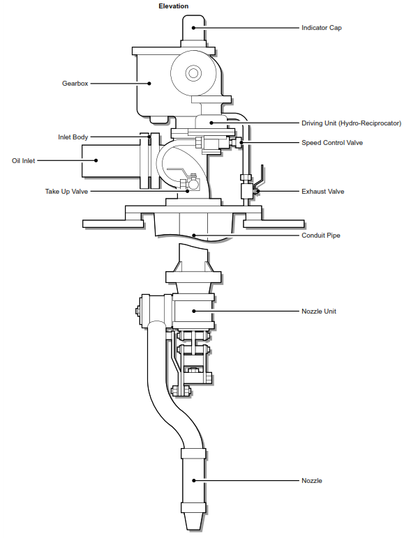
If it is necessary to carry out spot washing, then the operator must consult the shadow diagrams to work out the horizontal and vertical angle. The machine should be hand cranked to the vertical and horizontal positions and then the wash fluid valve can be opened. To adjust the vertical angle insert the crank handle to the vertical adjuster and turn it counter clockwise. To adjust the horizontal position of the nozzle insert the crank handle to the adjuster on the side of they hydro-reciprocator and turn it counter clockwise.
Deck Mounted Machines
It is not intended for these machines to be removed from the tanks unless there has been an actual mechanical failure. In the event of such a failure, a lifting tripod, chain block and tools are provided and should be kept in good order.
Normal maintenance will consist of running each machine periodically for three minutes to verify that the machine is carrying out its programme and the stop valves are tight when not in operation. If testing each machine with drive fluid is not possible, routine checks can be carried out by manually rotating the nozzle horizontally ten times and changing the vertical angle by 30°. On a yearly basis remove the gearbox cover, grease the gears and ball bearing parts, that the machine is carrying out its programme and the stop valves are tight when not in operation.
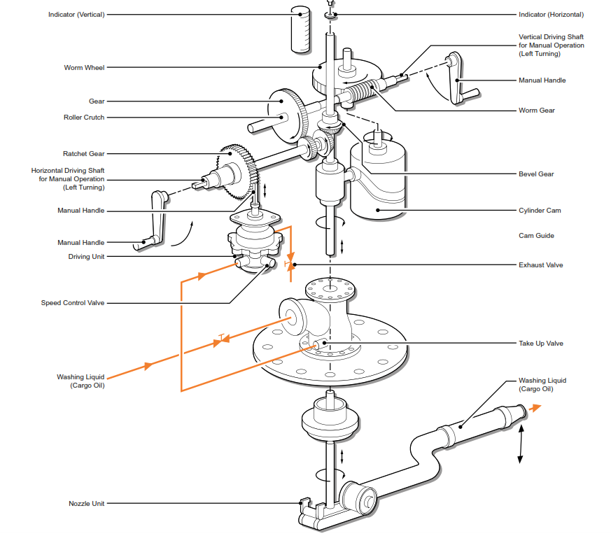
Tank cleaning machine detail