System as per my present vessel
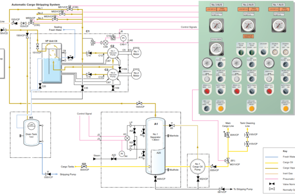
The automatic cargo stripping system is provided to improve the efficiency of stripping the cargo oil tanks and to assist in the maintenance of high bulk rate discharge. It utilises the cargo oil pumps to complete the stripping operation which reduces unloading time. The operation is fully automated.
The basic principle of the system is to automatically prevent the suction of gas into the pump, thus enabling the cargo oil pump to complete the discharge without using a conventional small capacity reciprocating pump.
The gas drawn in from the bellmouth tank suction and the cargo oil vapour produced in the suction line are separated from the cargo oil in the separator, on the suction side of the cargo oil pump. The gases gather at the top of the separator from where they are extracted by the vacuum pump system.
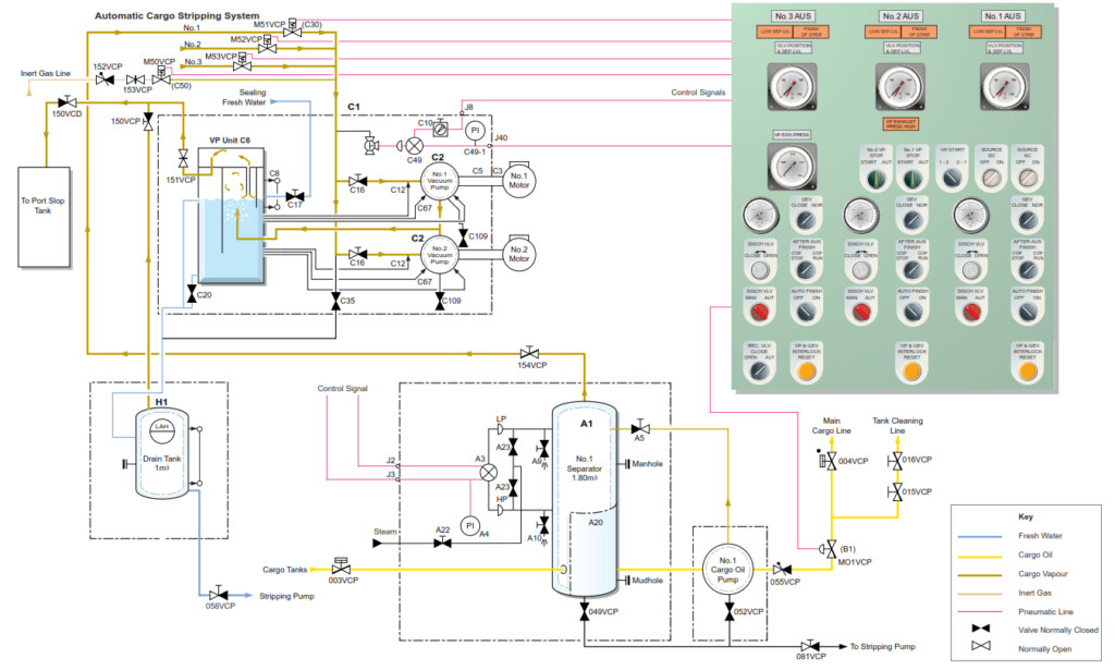
When a large volume of gas enters the separator during the stripping stage, the liquid level in the separator drops. This would normally cause the pump to lose suction and stop pumping. To prevent this condition, the discharge valve of the cargo oil pump is throttled in proportion to the liquid level of the separator and adjusts the flow rate accordingly. The lower the liquid level falls, the more the discharge valve closes, for this operation the discharge valve B1 (switch DISCH VLV. MAN/AUT) must be set in automatic (AUT) mode and the gas extraction valve set to normal (NOR) operation (switch GEV CLOSE/NOR) on the AUS control panel. When a preset level is reached in the separator (50%) the vapour vacuum extraction pumps cut in to draw off the vapour in the separator, this will then cause the liquid level to rise and the discharge valve is opened accordingly.
Component Description
Separator (A1)
No. of sets: 3
Capacity: 1.8m3
The separator is a tank on the suction side of the cargo oil pump. It contains an integrated lattice screen (A20), which assists in the separation of the gas from the liquid and protects the pump from damage by ingress of debris. The vapour collects at the top of the separator where it is extracted by the vacuum pump system (C2).
A level transmitter (A3) is mounted on the side of each separator. The transmitter converts the liquid level to a pneumatic signal which controls the discharge valve (B1), vacuum pumps (C2) and gas extraction valve (C30). The outlet pipe from the separator is fitted with a float device which should stop any carry over of the cargo oil when the separator is primed.
Discharge Control Valve (B1)
No. of sets: 3
Type: Pneumatically operated, non-tight butterfly valve
The discharge control valve (B1) is a butterfly type valve driven by a pneumatic cylinder and controls the pump capacity. The valve is controlled remotely either by the automatic control signal from the level transmitter (A3) on the separator, or by the manual control signal from the manual loader on the control panel in the cargo control room. The selector switch is used to select automatic or manual control of the discharge valve. Three-way cocks are situated locally to enable the discharge valve to be opened in an emergency.
A valve position gauge (black indication needle) which is integrated with the separator level gauge (red indication needle) is located on the AUS control panel in the cargo control console and indicates the position of this valve.
Vacuum Pump Unit (C1) and Vacuum Pumps (C2)
Capacity handling of vacuum pump unit: 320m3/h Maximum Vacuum: -0.073MPa No of pumps 2
There is a single vacuum pump unit which can draw off vapour from the separators. The vacuum pumps are of the horizontal water ring type, each driven by an electric motor through an intermediate shaft which passes through the bulkhead from the engine room. The pumps extract the gas from the top of the separators (A1) and discharge it to the port slop tank. The vacuum pumps (C2) are automatically started and stopped by a pressure switch which is operated by the pneumatic signal from the level transmitter (A3). The pumps can also be started and stopped by means of the control switch on the control panel in the cargo engine control room.
Each pump is equipped with a screw-down non-return suction valve (C16) to prevent sealing water and gases from flowing back to the gas extraction line. The sealing water tank (C6) separates the gas from the sealing water and acts as a reservoir for the supply of sealing water to the vacuum pumps.
Gas Extraction Valve (C30)
No. of sets: 3 (one fitted to each separator)
The gas extraction valve (C30) is a pneumatically operated piston type valve. The three valves, one from each separator are located at the pump room entrance level. Each valve is installed in the gas extraction line leading from the top of the separator (A1), and is opened and closed by a solenoid valve controlled through a pressure switch, which is operated from the level transmitter (A3). The extraction valve opens when the separator level is less than 50% and closes when it returns to 70% or more.
Drain Tank (H1)
Any liquid (fresh water or cargo oil) which overflows or is drained down from the vacuum pump unit is stored in this tank which is emptied by the stripping pump via non-return valve 058VCP. The tank has a local sight glass and sounding pipe; the drain tank has a capacity of 1m3.
Note: During normal operations, one vacuum pump unit is running and the second is in standby mode.
Operating Procedure
Setting Up the System for Automatic Stripping
At the beginning and during the majority of the bulk discharge it is not always necessary to have the AUS system set to automatic operation. It is only when the separator(s) level begins to fall is it necessary to have the AUS system in automatic mode.
a) Ensure that there is sufficient water in the vacuum unit sealing tank. The level can be topped up by opening valve C17.
b) On the AUS automatic unloading console set the DISCH VLV MAN/AUTO switch to AUTO for each main cargo pump in operation that is nearing the stripping phase. The discharge valve will now be controlled by the separator level transmitter.
c) Set the gas extraction valve close/normal selector (GEV) to NOR. This will allow the gas extraction valve on each separator to operate automatically.
d) Set the recirculating valve (REC VLV) AUTO/CLOSE/OPEN selector to AUTO. This sets the recirculation valve C50 to operate automatically. This valve will now be controlled by the operation of the extraction valves and vacuum pump running condition. When all of the extraction valves are closed, valve C50 will open, this will then purge the line to the vacuum pump(s) with inert gas before they are stopped.
e) If it is required that a COP is to be stopped automatically by the AUS control system when it is finished discharging its last set of tanks, then set the after strip COP STOP/COP RUN selector to STOP for the selected cargo pump. This will cause the cargo pump to stop when the FINISH OF STRIP lamp flashes and the buzzer sounds, also the AUTO FINISH ON/OFF selector on the selected pump must be switched to ON.
f) Setting the automatic unloading system AUTO FINISH ON/ OFF selector to ON will cause the vacuum pump to stop and the gas extraction valve to close when the FINISH OF STRIP lamp flashes and the buzzer sounds.
g) Set both vacuum pump switches (No.1 VP and No.2 VP) to AUTO, this allows the vacuum pumps to be available as required.
h) Set the SOURCE AC and SOURCE DC switches to ON.
While the liquid level in the cargo oil tank is above 70% of the separator level the automatic unloading system is not required.
As the tank level falls, the suction pressure also falls and approaches the vapour pressure of the liquid being pumped. Part of the liquid will turn to vapour and accumulate at the top of the separator (A1) and, as a result, the separator level begins to fall.
When the separator level falls below 50%, a pressure switch is actuated by the pneumatic signal from the level transmitter (A3) and the vacuum pump (C2) starts. At the same time the gas extraction valve (C30) opens and the discharge valve (B1) is throttled in by a corresponding amount.
The vacuum pump extracts the gases and the separator level rises. When the separator level recovers above 70%, the gas extraction valve C30 closes and the IG purge valve C50 opens, 20 seconds later the vacuum pump stops. The discharge valve (B1) then opens.
As the tank level falls further towards the bottom of the tank, turbulence occurs around the suction pipe and gas begins to be drawn into the bellmouth of the tank suction. This gas is separated in the same manner as previously described.
When the tank level falls further, the liquid surface around the bellmouth becomes violently disturbed and a large volume of gas can be drawn in from the bottom of the bellmouth. Under these conditions the level of liquid in the separator falls to a level where the signal air pressure from the level transmitter causes the discharge valve to close and decrease the flow. The speed of liquid flowing into the bellmouth decreases and the disturbance around the bellmouth also decreases, thus the amount of gas being drawn into the bellmouth decreases.
When the volume of gas being drawn into the bellmouth becomes less than the extraction capacity of the vacuum pump, the separator level begins to rise and at the same time the discharge valve begins to open gradually and the pump discharge flow begins to increase.
This cycle will repeat until the discharge valve is opening only slightly while the amount of gas drawn in is increasing. When the separator level falls to below 5%, the red lamp LOW SEP LVL, on the control panel lights up, showing that unloading has reached the stripping stage.
As the stripping of the cargo oil tank advances, even though the vacuum pump is running continuously, the level in the separator does not rise. As a result the discharge valve remains closed most of the time.
When the low separator level lamp has remained on for three minutes the red lamp FINISH OF STRIP flashes and the buzzer sounds, signifying completion of discharge.
If the COP stop/run selector switch has been set at COP STOP, then the cargo pump will stop automatically at this stage. However, if the switch has been set to COP RUN, then the cargo pump will continue to run. If the residual liquid appears to warrant more stripping it is possible to control the pump and the discharge valve manually, in which case set the AUTO FINISH ON/ OFF selector to OFF to release the trip condition of the vacuum pump and the gas extraction valve. This operation will allow the vacuum pump and gas extraction valve to return to automatic control if conditions warrant it. When it can be judged that there is no advantage in operating the pump continuously, the pump can be stopped manually.
CAUTION:Running the pump in the manual condition may result in the pump running dry, or running with the discharge valve closed longer than the manufacturer’s recommendation, resulting in serious damage to the pump and mechanical seals.
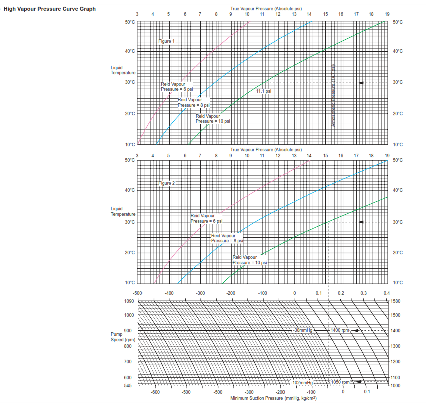
When the vessel carries high vapour pressure cargo (HVPC) which is classified as a cargo which has a Reid pressure above 8psi, there is the risk of excessive pump cavitation during discharge. This is due to the cargo boiling off under the effect of a low suction vacuum pressure.
When an HVPC type cargo is carried, strict observation should be made to the cargo pump suction pressure to ensure it does not fall below the minimum suction pressure. As the level in the cargo tanks fall to a low level, the suction pressure will increase, if this pressure falls below the minimum valve excessive vapour will be generated in the pump casing with resultant pump cavitation. The relationship between Reid vapour pressure, pump speed and minimum suction pressure for an HVPC cargo can be seen. In order to maintain the discharge within the limits there are two possible operations that can be used:
• Reduce the pump speed thereby lowering the minimum suction value. This will achieve the desired affect although it will increase the time taken to finish the cargo operations. The pump speed should be reduced in steps corresponding to the increase in the suction pressure. Consideration should be made of any limitations placed on the ship by the receiving terminal to maintain a minimum discharge pressure.
• Close in on the pump discharge valve when the minimum speed has been reached in order to maintain a required discharge pressure.
In order to help reduce the problems in pumping HVPC cargoes, consideration should be given to the tanks into which it is loaded. As a guide it is best to load these cargoes in the forward wing tanks if possible, in order that when the ship has a stern trim, the head from these tanks will be maintained for a longer period.