Principle of operation
The measurement technique used in the Oil Discharge Monitoring & Control System is based on scattered light. The sample of discharge water passes through a detector cell while light enters and leaves the measurement area of the cell. The sample flow is at right angles to the optical path. When no particles or oil droplets are present in the water, light can pass straight through the cell (Direct beam). When oil is present in the form of a homogeneous mixture, light is scattered at different angles (Scatter beam).
The intensity of scattered light at a specific angle depends on the density of oil droplets and upon their particle size relative to the wavelength of radiation. The intensity of light of the direct beam decreases logarithmically with increasing oil concentration, while the scatter beam increases linearly but passes through a maximum before decreasing logarithmically.
The maximum occurs because of the increase in attenuation blocking out the scattered light at high concentrations. The variation of light refraction by oil droplets only is quite different to that refracted when solid contaminants are also present and this fact can be used to obtain an accurate indication of oil content whilst disregarding solid particles up to a point.
The light source used in the Oil Discharge Monitoring & Control System is a near infra red diode which is operated in the pulsed mode so that the average power dissipation is very low, although the intensity is high. The light signal is processed and transmitted along a communication cable from the detector cell to the EPU (Electro Pneumatic Unit) where the three detection signals are used to compute the oil concentration levels present in the sample passing through the detector cell.
At the end of the start up flushing cycle a system zero check is performed, this automatic zero setting compensates for any small deposits on the cell windows. The window wash pump cleans the cell windows at regular intervals.
All operating controls and system alarms are situated on the MCU. Manual system flush and window wash controls are available to make these two operations possible at any time. With the exception of selecting the sample point and the oil type, the system works automatically once sampling has been initiated. The oil level together with the discharge flow rate and ships speed are input to the MCU to give a permanent record of oil discharged overboard. Both calibration alarms and operational alarms are provided and the alarm philosophy employed follows normal marine practice.
When a fault occurs, both audible and visual alarms are activated. The audible alarm can be silenced by fault acceptance but the visual alarm cannot be extinguished. It is only after the fault has been rectified that the visual alarm is extinguished. Should a second alarm occur during this sequence, both audible and the visual alarms would be reactivated.
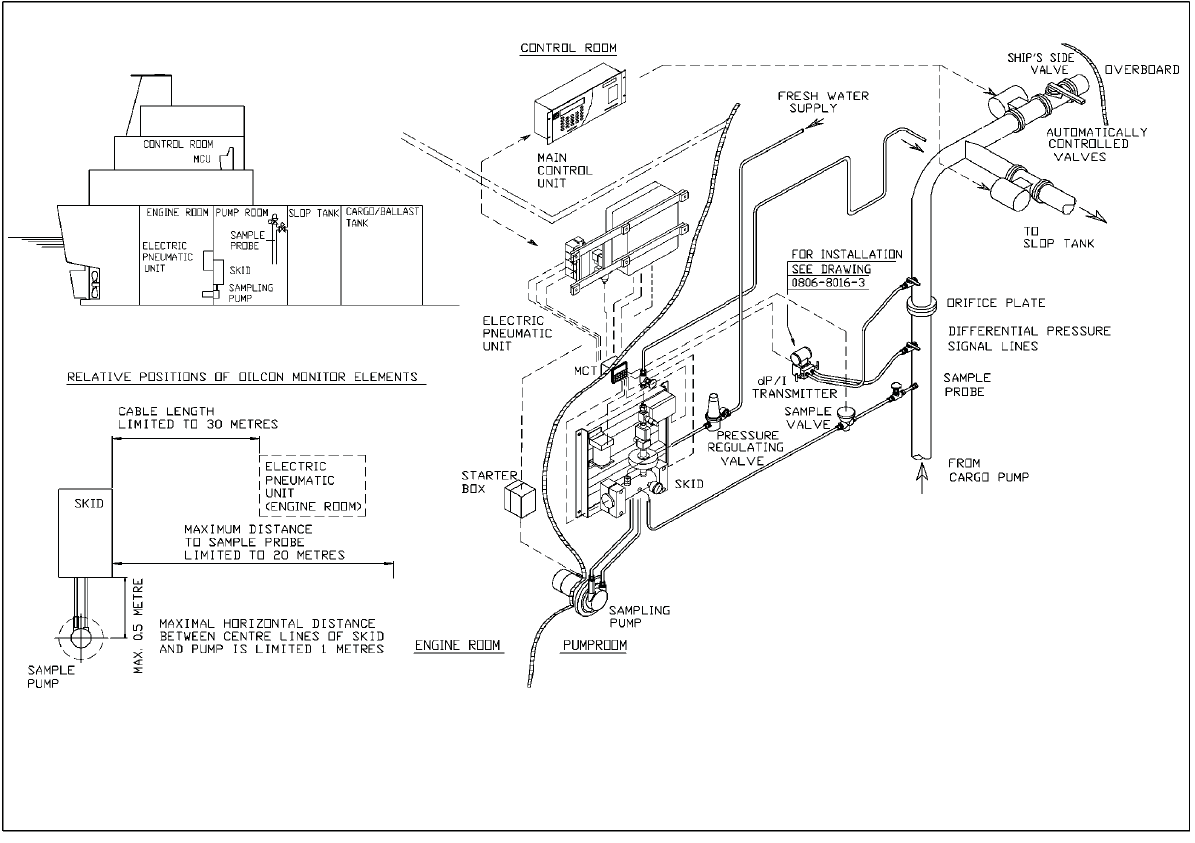
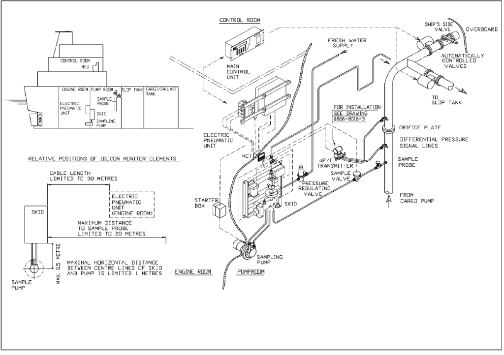
Sampling system arrangements
The sample point is selected from the MCU in the Ships Cargo Control Room; this causes the selected valve to open. When the system is in Sample mode, water is drawn from the sample point by the sample pump, passed through the detector cell and then discharged to the slop tank or discharged overboard, depending on the installation.
The accuracy of the monitor is improved by the use of a flushing sequence before sampling commences, at intervals during sampling and when the system is shut down after use. All the flushing sequences are carried out automatically by the system. The flushing sequences serve three purposes:
► to clean the pipework;
► to keep the detector cell windows clean, which keeps the optical path unobscured and
► to perform a zero check every time a flush sequence is activated.
The flushing sequences can be operated manually from the MCU, if required.
The Skid Assembly, contains a pneumatically operated shuttle valve, which facilitates the forward flush and backward flush. During the automatic flushing sequences on start up, and on shut down, the valve activates to flush all the pipework using the fresh water supply and sequentially selects between backward and forward flush. When the manual flush is operated, valve activates to allow fresh water into the system and an additional zero check is performed.
Every three minutes during sampling, an automatic cleaning of the windows in the detector cell is carried out. A pneumatic pump mounted in the Skid Assembly supplies high pressure fresh water which is sprayed across each window.
The use of fresh water for these sequences means that it is important, for correct operation of the Oil Discharge Monitoring & Control System, that an un-interrupted supply of fresh water is available. The fresh water used must be free of any contaminants.
Various Components
Oil Discharge Monitoring and Control System
The Oil Discharge Monitoring & Control System continuously samples the ballast water being discharged overboard and measures the oil content and controls the discharge of the ballast water and plays therefore, a central role in the Oil Discharge Monitor & Control System.
Main Control Unit (MCU)
The Main Control Unit is the central part of the Oil Discharge Monitoring & Control System.
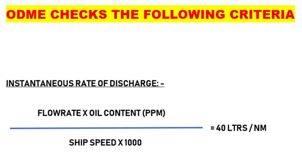
Its function is to compute and record:
– the instantaneous rate of discharged oil, in litres per nautical mile;
– the total quantity of oil discharged into the sea on each voyage;
– to control the ships overboard discharge system.
It receives the following input signals:
– ships GPS input
– ships speed in knots;
– overboard valve position;
– oil content of ballast water in ppm;
– rate of discharge of ballast water in tonnes per hour.
Electro Pneumatic Unit (EPU)
The Electro Pneumatic Unit (EPU) contains the control electronics and the solenoid valves to switch the pneumatic signals. It also contains the zener barriers for the input signals from the flowmeter(s), flow switch and measurement cell.
Pump/motor assembly
The Pump/Motor assembly comprises a high-shear vortex pump, a gas tight bulkhead seal and a motor. The pump provides a degree of sample water conditioning as the shearing effect tends to produce droplets of oil of roughly similar size.
Skid assembly
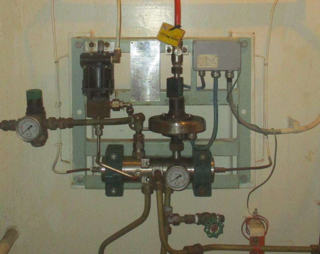
The Skid Assembly contains the necessary items to handle the sampled ballast water and to measure the oil content. In the Skid Assembly there is a pneumatically operated shuttle valve, and a window wash pump.
The shuttle valve selects between fresh water, forward or backward flush and sample water.
Also contained within the Skid Assembly is the detector cell which contains the electronic sensing system to determine oil content. On the left hand side of the Skid Assembly is the Window Wash pump.
This is a pneumatically operated pump which provides a 10 to 1 pressure boost to the window flushing water.
Also included in the Skid Assembly is a flow setting valve , which sets a back
pressure on the Sample pump and a magnetic flow sensor (2) to determine flow through the Skid assembly.
The Skid Assembly is normally mounted in the pump room opposite the EPU on the engine room side of the bulkhead.
Flowmeter system
The flow of water through the orifice plate causes a pressure difference across the plate. This differential pressure is converted into a mA signal and transmitted to the EPU by the dP/I transmitter. The manifold valve block fitted to the differential pressure transmitter, has three shut-off valves. The two outer valves are for blocking off the pressure sensing lines from the sensor. The centre valve serves as equalizing valve to balance the pressure at both sides of the transmitter.