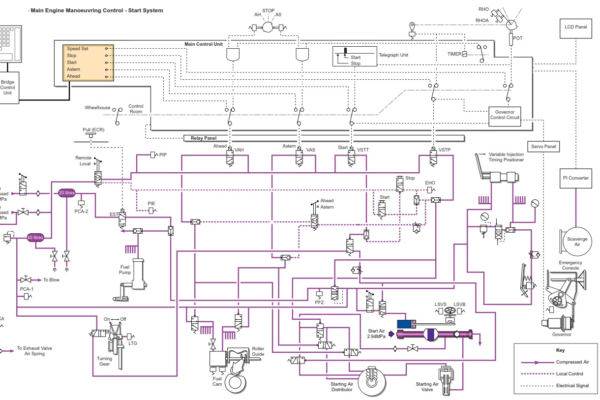
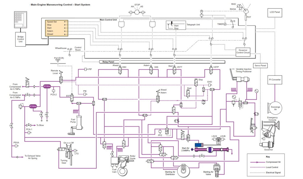
Introduction
The Bridge Maneuvering System is a bridge maneuvering system used for the remote control of the ship’s main diesel engine which is connected to a fixed pitch propeller. The maneuvering system allows for remote engine control from the bridge or engine control room. Control may be transferred between these stations and may also be transferred to the local engine side control stand which has priority at all times; the local control stand takes control it is not given control.
The maneuvering system is composed of five sub-systems as follows:
• The Engine Control System (ECS) which provides full automatic control from the wheelhouse.
• The Engine Protecting System (EPS) which monitors the engine systems and initiates alarms, engine slowdown or engine shutdown in the event of extreme conditions which could cause engine damage.
• The Engine Telegraph System (ETS) which provides communication between the wheelhouse and engine control room and the engine side control stand.
• The Engine Manoeuvring System (EMS) which provides for manual control of the main engine from the engine control room.
• Electronic Governor System (MAG) which regulates the fuel supply to the engine cylinders in order to control the engine’s speed.
Control Panels
There are control panels in the wheelhouse console and in the engine control room console. There is a local (emergency) control stand at the engine side and this location is provided with a telegraph receiver and pushbuttons for cancelling slowdowns and shutdowns and for operation of the electrically driven auxiliary blowers.
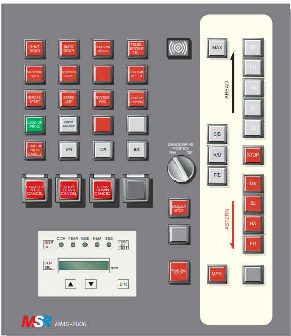
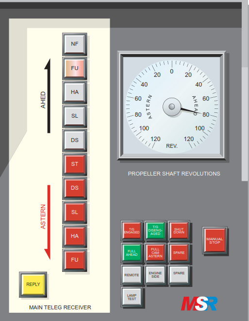
Bridge (Wheelhouse) Panel
The bridge maneuvering system panel is fitted in the main wheelhouse console and contains a telegraph transmitter unit and other devices for operating and monitoring the main engine.
The telegraph transmitter unit is switch operated with illuminated indicators for the selection of each engine speed, ahead or astern. When the telegraph switch is moved to a new position the indicator is illuminated showing which movement has been selected. When in bridge control, movement of the telegraph transmitter to a new position automatically activates the control system to operate the main engine according to the new order. When in engine control room control, the telegraph transmitter acts as a communication unit to transmit orders to the engine control room. In this case when the telegraph transmitter is moved to a new position, the illuminated indicator at that position flashes and when the engine room telegraph is moved to the position to acknowledge the new command, the indication stops flashing and becomes fully illuminated. An associated buzzer operates until the new command is acknowledged.
Bridge Telegraph Unit
The sub-telegraph has three illuminated pushbuttons located to the left of the main telegraph transmitter. These are S/B (Standby), R/U (Run up) and F/E (Finished with engines). When any of these pushbuttons is pressed the indicator illuminates.
The manoeuvring panel includes an emergency stop pushbutton marked MANUAL STOP, and a buzzer stop pushbutton. In addition there is a selector switch for selecting the engine manoeuvring position, either the wheelhouse (W/H) or the engine control room (C/R).
At the upper left of the maneuvering panel are a number of illuminated indicators which are illuminated when the action shown at the indicator is taking place; these indicators show the following.
• Shutdown
• Slowdown
• Fuel Cam Abnormal
• Telegraph System Fail.
• Shutdown Cancelled
• Slowdown Cancelled
• Critical Speed
• Impossible Start
• Speed Limit
• System Fail
• Start Air Low Pressure
• Load Up Program
• Cancel Available
• Load Up Program Cancelled
• Wheelhouse Control
• Control Room Control.
• Engine Side Control.
Below the indicators there are three illuminated pushbuttons to activate the following.
• Load Up Program Cancel
• Shutdown Cancel
• Slowdown Cancel.
At the bottom left of the wheelhouse manoeuvring panel the Telegraph Logger front panel is located. This provides a printout of all engine movement instructions on a paper roll. The panel contains a dimmer pushbutton, a lamp and buzzer test pushbutton, a selector pushbutton for Month/Day or Hour/Min and a display selector pushbutton for changing the display from engine RPM to time or vice versa. Two arrow pushbuttons allow for setting of the time when the display is showing the time. Five LEDs at the top of the telegraph logger panel show which features are selected. At the rear of the telegraph logger there are switches and pushbuttons associated with the printer unit; these are a test print pushbutton, a wind pushbutton, a reset pushbutton and a FREE/ LOCK selector switch. When LOCK is selected printing is not done but 100 lines of printing content are memorised.
The bridge manoeuvring console also contains the Oil Mist Slowdown panel. This contains two illuminated indicators for Oil Mist Slowdown and Oil Mist Slowdown Cancel. There is a LAMP TEST pushbutton and an OIL MIST SLOWDOWN CANCEL pushbutton which is pressed if the bridge desires to cancel the automatic oil mist slowdown. The panel also has a dimmer dial.
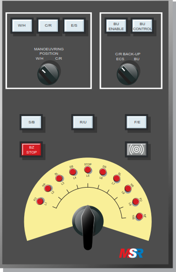
Engine Control Room Panel
The engine control room maneuvering panel has two parts, the main control unit and the backup control unit.
The main control unit has a selector switch for selecting the maneuvering position, wheelhouse or engine control room. Above the selector switch are illuminated indicators which show which location has control, wheelhouse, engine control room or engine side. Another selector switch allows for selection of the backup control system if required and indicators show whether the main control or the backup unit has control of the engine.
Engine Telegraph System
Below the selector switches there are the sub-telegraph indicators for Standby, Running Up and Finished with Engines, and below these are the buzzer and the buzzer stop pushbutton. At the bottom of the panel is the telegraph receiver which is used to select ahead or astern operation when maneuvering from the engine control room main panel. Associated with the main panel is the emergency engine stop pushbutton which is located under a cover.
The engine speed control dial is located near the telegraph receiver, and this is used for starting and stopping the engine from the engine control room. The dial is turned to the STOP position in order to stop the engine and is turned to the START position in order to turn the engine over on air. When the engine reaches firing speed on air the speed control dial is turned to the desired fuel setting position and when the engine is running the speed is regulated by turning the speed control dial as required.
Backup Control System
The back-up control system is located in the engine control room and provided a means of controlling the main engine from the control room should the remote control system fail. The electronic governor system must still be operating for the back-up control system to operate. Orders are transmitted from the bridge by means of the telegraph and the engineer operates the back-up control unit to start, stop and regulate the speed and direction of the main engine.
Oil Mist Slowdown Panel
The engine control room manoeuvring console has an oil mist slowdown panel which contains two illuminated indicators for Oil Mist Slowdown and Oil Mist Slowdown Cancel. There is a LAMP TEST pushbutton and an OIL MIST SLOWDOWN CANCEL pushbutton which is pressed if the duty engineer desires to cancel the automatic oil mist slowdown.
The Bridge Maneuvering System LCD panel is fitted in the control room console, and this provides information to the duty engineer and a facility for the duty engineer to communicate with the maneuvering and control systems.
Engine side control stand
The engine side control stand is provided with a telegraph and indicator box. This unit contains a main telegraph receiver with indicator lamps showing the ordered speed and direction of the engine. Indicator lamps show the if the engine turning gear is engaged or disengaged, if the engine fuel cam is set for ahead or astern, whether the engine is in local or remote control, and if the engine is shut down. The box also contains an emergency (manual) STOP pushbutton and an engine speed indicator.
Engine Control System (ECS)
The ECS automatically controls the starting, stopping, speed regulation and reversing of the main engine under instructions from the wheelhouse via the telegraph transmitter. The following functions are provided by the ECS:
Control Position Changeover
The engine control position may be changed between the bridge (wheelhouse) and the engine control room, and between the engine control room and the engine local control stand.
Fuel Cut-off
When the engine is under certain conditions the control systems cuts off fuel from the engine cylinders and prepares the engine for the next starting operation. These conditions are as follows:
1) Engine STOP order.
2) Emergency shut down; when the Engine Protecting System is in emergency shut down state.
3) Air running; when the engine it turning over on air during a start procedure.
4) When an Impossible Start situation exists: see the Starting section below.
5) When the main engine rpm decreases to below the air to fuel changeover level (firing speed) for the ordered rotational direction, after the engine is put on to fuel after starting on air.
Starting
Main engine starting can be automatically carried out by moving the main telegraph transmitter switch one division, ahead or astern, from the STOP position. The starting sequence is completed when the main engine is operating under stable conditions on fuel. In order to monitor the engine behaviour at starting a number of safety functions are provided as follows.
Start Blocking.
The engine cannot be started when it is in one of the following states:
• Stop order
• Emergency shut down
• Impossible start
• When reversing: the main engine rpm is higher than the speed level for operation of the braking air system
• Turning gear is engaged
Repeat Start and Three Failed Starts
If the engine speed is below the air to fuel changeover level (firing speed) after the engine goes to fuel running, the control system considers this to be a misfire and fuel supply to the engine cylinders is shut off. If this situation continues for 6 seconds, the control system does the following simultaneously:
• Cancels the scavenge air fuel limiter in the governo and
• Repeats engine starting using normal start procedure
If there are three successive engine misfires further starts are blocked and the ‘3 Failed Start’ indicator is highlighted.
Impossible Start
Uunder any of the following states the alarm ‘Imposs Start’ is activated.
• Three failed starts
• Start too long: when air on the engine continues for 8 seconds during a normal start
• Start circuit abnormal: when the auxiliary blowers are stopped
• Non fuel cut off: when stopping the fuel has not been cut off
Any of the Impossible Start conditions, except the auxiliary blowers not operating, may be reset by moving the telegraph handle to the STOP position after the cause of the impossible start has been corrected. The impossible start condition due to the auxiliary blowers not operating is automatically reset when either of the two auxiliary blowers starts to operate.
Speed Limit
In order to avoid running the main engine under overload or critical conditions the following speed limiters are provided.
1) Critical Speed Avoidance. This automatically prevents operation of the main engine in the critical speed zone even if the telegraph control requests such a speed operation. The rpm set point is limited to the lowest speed of the critical speed zone.
2) Emergency Slowdown. When the Engine Protecting System is activated under emergency slowdown the maximum RPM setpoint is limited to the slowdown speed level in order to restrict the maximum speed of the engine. This prevents sudden increase of the engine speed after resetting of the emergency slowdown.
3) Manual Speed Limit. When operating under bridge control the speed control dial in the engine control room console acts as a limiter for the maximum allowed speed of the main engine. When this feature is limiting the rpm set point to the engine governor the indicating lamp ‘Speed Limit’ is illuminated.
RPM Control
Speed regulation of the main engine is achieved by moving the telegraph lever to the desired speed and direction position. The signal from the telegraph transmitter is converted into an rpm set point and this is used by the governor in order to regulate the engine speed by control of the fuel supply to the cylinder fuel injectors.
Load Up Program
This is a feature which is designed to limit rapid variations in engine speed and thermal loading when an increase to full sea speed is requested. The engine speed is increased slowly by the load up program provided that the following conditions are satisfied.
• The main engine is in the ahead speed increase process.
• The rpm set point is higher than the load up program starting level.
• The ‘Load Up Prog. Cancel’ is OFF.
• The lamp SPEED LIMIT is not illuminated.
When the load up program is operating the lamp ‘Load Up Prog.’ is illuminated.
It is possible to bypass the load up program, if necessary, by pressing the LOAD UP PROG. CANCEL pushbutton.
Reversing
When the telegraph transmitter selects a movement in the direction opposite to the current rotational direction of the engine, the starting air distributor is changed over to the ordered position and braking air is injected into the engine cylinders and the engine is then started on air in the ordered direction. If the telegraph transmitter STOP position was selected when a new direction was ordered the braking air is not supplied unless the engine was still rotating in the old direction.
Crash Astern
A crash astern operation is carried out by selecting an astern position on the telegraph transmitter when the engine has been running in the ahead direction for more than 4 minutes at a speed above a predetermined harbor value. In order to prevent a misfire, the scavenge air fuel limiter in the governor is cancelled for about 30 seconds.
Cancelling the Fuel Limiter
The scavenge air fuel limiter in the governor is cancelled under the following conditions in order to ensure ignition:
• Repeat start
• Crash astern movement
When the scavenge air fuel limiter is cancelled the ‘Scav. Limit Cut Out’ indicating lamp is illuminated.
Operation Test
The operation test checks most of the engine control system functions without affecting the state of the main engine. The systems for carrying out the operation test are provided in the LCD panel located in the engine control room console. The operation test can only be carried out when the engine is stopped.
System Malfunction
The bridge ‘System Failure’ alarm and the engine control room ‘WCS System Malfunction’ alarms are activated whenever any of the following malfunctions occur:
• Microprocessor abnormal
• Control room speed dial potentiometer abnormal
• Scavenge sensor abnormal
• Actuator abnormal
• Control room communication failure
• AIO source failure
• Wheelhouse communication failure
After the cause of the malfunctions has been traced and corrected the ‘Cause Reset’ pushbutton on the LCD panel must be pressed.
Speed Block
When both RS-422 communication lines between the bridge and the control room fail the engine is maintained at the current status. If one RS-422 communication link fails the engine is controlled normally.
System Failure
The ‘System Failure’ alarm is activated in the wheelhouse when any of the following abnormalities occur.
• Power failure of the Engine Control System
• System malfunction in the Engine Control System
• Power failure of the Engine Protecting System
• System malfunction of the Engine Protecting System
Engine Telegraph System (ETS)
The engine telegraph system comprises the main telegraph system and the sub- telegraph system and these function as described below.
Main Telegraph System
This system directly or indirectly issues orders concerning the maneuvering of the main engine. Its functions differ depending upon which control location has control.
1) Bridge (Wheelhouse) Control. The main telegraph transmitter has a built-in order transmitter which issues stepless control signals to the ECS thus controlling the state of the engine. The main telegraph receivers in the engine control room and at the engine side control stand indicate the state of the order issued by the main telegraph transmitter. When the main telegraph transmitter issues a new order an audible indication is given for about 2 seconds.
2) Engine Control Room and Engine Side Control. The main telegraph acts as a communication unit between the wheelhouse and the control room or engine side, whichever currently has engine control. When a new order is issued at the wheelhouse unit this is audibly indicated at the control room and engine side units showing that a new engine order has been made. The new order is shown at the telegraph receivers in the control room and at the engine side. The telegraph receiver knob is moved to the new indicated position, and this silences the buzzer.
When under engine control room control movement of the telegraph receiver knob determines the rotational direction of the next engine movement (it is part of the engine control system). When under engine side (local) control the telegraph receiver acts as a communication unit only and has no control over the engine.
Sub-Telegraph System
Communication between the wheelhouse and engine control room using the sub-telegraph system is independent of the main telegraph system. Issue of a new order at the wheelhouse unit causes a buzzer to sound in the control room unit and a lamp at the desired order position in the control room unit to be illuminated. When the reply to operation to the new order is carried out at the sub-telegraph receiver the lamp indicating the new order stops flashing and remains fully illuminated; at the same time the buzzer stops.
When under standby orders, pressing the BUZZER STOP pushbutton stops the buzzer and the buzzer then only sounds for 2 seconds when a replay operation is carried out.
Telegraph Logger
The telegraph logger records all movements issued by the main telegraph system and sub-telegraph system.
When under bridge control engine orders are recorded together with the date and time. When under engine control room control or engine side control, with either the main telegraph or sub-telegraph, the order and reply details are recorded together with the time in each case.
The logger clock is linked to the ship’s master clock and the time can be confirmed by pressing the time function key in the bridge panel.
Engine Maneuvering System (EMS)
The engine maneuvering system is used to manually control the operation of the main engine from the engine control room. Instructions are issued to the engine control room from the bridge by means of the main telegraph system and the duty engineer in the engine control room operates the main engine in accordance with those instructions. Control of the engine is exercised by means of the telegraph receiver knob for selection of the rotational direction of the engine (see section Main Telegraph System above) and the speed control dial is used for starting and stopping the engine together with regulation of the speed. The speed control dial is located with the main telegraph unit in the maneuvering section of the engine control room console.
Stopping
The speed control dial is turned to the STOP position and the engine maneuvering system cuts off the fuel supply to the main engine whilst a stop signal is sent to the governor.
Starting
a) The speed control dial should be in the STOP position.
b) In response to the order from the bridge the engine control room telegraph receiver knob is turned to the desired position; this silences the buzzer and activates the reversing system for the engine should a new rotational direction be requested. The solenoid valve for reversing is energized, the air distributor changes to the new position and the fuel cam roller guide changeover mechanism operates.
c) Turn the speed control dial to the START position. A governor start level signal is sent to the governor, the output shaft of the governor actuator moves to the start limit position, the solenoid valve for engine starting is energized and the engine commences to turn over on starting air in the desired direction.
d) When the engine speed reaches the air-fuel changeover level (engine firing speed), the speed control dial is turned to the desired engine speed position. The solenoid valves for engine stopping and starting are de-energised at the same time. The engine speed is regulated to the governor start level for 6 seconds and then it is regulated to the ordered speed.
e) When the engine is running further speed changes are made by turning the speed control dial to the appropriate position.
Start Blocking
The main engine cannot be manually started if the emergency shutdown is active or if the turning gear is engaged.
Misfire
If a misfire occurs the engine will not pick up speed on fuel and will stop. The engine can be restarted and there is no limit on the number of manual restart attempts which may be made. However, if the engine fails to start after three manual attempts it indicates that there is a fault somewhere in the maneuvering system and an investigation should be carried out and the fault rectified before further starting attempts are made.
To restart after a misfire:
a) Turn the speed control dial to the STOP position. If necessary, press the SCAV. LIMIT CUT OUT pushbutton on the LCD panel in order to cancel the scavenge air pressure fuel limiter in the governor.
b) Turn the speed control dial to the START position.
c) When the engine reaches firing speed turn the speed control dial to the desired engine speed position. If the engine fails to reach firing speed it generally indicates that there is a fault in the starting air system. If the engine reaches firing speed but fails to pick up speed when fuel is supplied, it indicates a fault in the fuel system. A check should be made to determine if any of the cylinders are firing, if so then the problem is in the individual cylinder fuel systems rather than in the general fuel or governor systems.
Longer Air Running
If the engine fails to reach firing speed within a reasonable time the speed control dial should be returned to the STOP position in order to avoid excessive consumption of starting air. The cause of the failure to reach firing speed should be investigated.
Speed Limit
The control system prevents the engine from operating in the critical speed zone even if the speed control dial is turned to a speed setting which is in the critical speed zone.
The main engine speed is regulated by the governor rpm set point which may be lower than the speed control dial setting. The load up program does not function when operating under engine room control of the main engine and so care must be taken in increasing engine speed in order to avoid thermal stressing.
Reversing
Manual reversing of the engine may be achieved as follows.
a) Turn the telegraph knob to the desired direction of rotation, ahead or astern. The solenoid valve for engine stopping is energized, the output shaft of the governor actuator is set to zero and fuel is shut off the engine.
b) Turn the speed control dial to the STOP position. The reversing solenoid valve for the desired rotational direction is energized, the distributor changes to the ordered position, and the changeover mechanism on the fuel cam roller is activated.
c) When the engine speed is lower than the reversing enabled level (assuming that the engine is still running in the opposite direction from that ordered), turn the speed control dial to the START position. The starting solenoid valve is energized, the governor actuator output shaft moves to the start position, braking air reduces the engine speed to if it is still running in the opposite direction) and starting air is applied to turn the engine in the new ordered direction. Under crash astern conditions the scavenge air pressure fuel limiter in the governor is automatically cancelled for 30 seconds.
d) When the engine is rotating at the firing speed in the new direction turn the speed control dial to the desired speed. When the engine picks up speed on firing the starting and stopping solenoids are de-energized, and the governor regulates the engine speed to the desired value after maintaining it at the governor start level for 6 seconds.
System Malfunction
If the potentiometer of the speed control dial fails, the ‘System Failure’ alarm is activated in the wheelhouse and the alarm ‘ECS System Malfunction’ is activated in the engine control room. When the cause of the malfunction is corrected the system is reset by pressing the CAUSE RESET pushbutton in the engine control room console LCD panel.
Speed Blocking
Should the speed control dial potentiometer failure whilst the engine is being maneuvered from the control room the engine is kept running at the speed and in the direction which were last set. If bridge control is available, the engine control should be changed to the bridge but if it is not the engine control should be changed to the local control station. When the cause of the malfunction is corrected the system is reset by pressing the CAUSE RESET pushbutton in the engine control room console LCD panel.
Wrong Way Alarm
If the engine rotates in the direction opposite to that ordered by the main telegraph the emergency shutdown solenoid valve is energized and a signal is sent to the governor cutting off the fuel supply to the main engine. At the same time the WRONG WAY lamp starts flashing and an alarm buzzer is activated. The cause of the wrong direction of rotation should be investigated, corrected and the engine restarted.
Engine Control
The engine may be maneuvered from the engine control room, the bridge or the engine side local (emergency) stand.
Control Room Control
The valve 100 at the engine side control stand must be turned to the REMOTE position and the fuel linkage must be connected to the governor so that speed control can take place through the governor. The maneuvering switches in the wheelhouse panel and in the engine control room panel must both be in the C/R (control room) positions. The illuminated indicators in the wheelhouse and control room will show which station has control.
Instructions are relayed from the bridge to the engine control room through the telegraph system.
There are three basic control orders which can be issued to the engine, Start, Stop and Run and these are the three control modes.
Stop Mode
In stop mode the stop signal is sent to the engine and if the engine is running it will stop. Stop mode is activated by turning the speed control dial in the control console to the STOP position.
Before maneuvering takes place, the auxiliary electric blowers must be selected for automatic and must be started; they will operate when the scavenge air pressure falls below 0.7MPa falling and stop on 0.5MPa rising.
When the engine is in the stop mode it may be started and may also be reversed. Reversal of the engine is undertaken by moving the telegraph knob ahead or astern as required. The telegraph knob is moved in order to acknowledge an instruction passed to the engine control room from the bridge and turning the telegraph knob to the position indicated by the illuminated order at the telegraph, signals to the wheelhouse that the engineer at the control will undertake the requested engine movement.
If the movement requested calls for an engine reversal, turning the telegraph knob to the ahead or astern position causes the control system to reposition the fuel pump roller guides for engine running in the opposite direction and activates the starting air distributor cam for starting in the new direction. The engineer should not start the engine until the air distributor and fuel pump rollers are correctly set.
Start Mode
An engine start is made by turning the speed control dial to the START position. This activates the starting air system, and the engine will turn over on air. A start cannot be made if the telegraph receiver is in the STOP position or if the turning gear is still engaged.
Run Mode
When the engine is rotating on air at a speed above a certain minimum, the firing speed, the fuel control dial may be turned from the START position to a number which is the fuel pump index setting. The engine will fire on fuel and the engine speed will increase. The engine speed will be set to the governor start level for 6 seconds even though the speed control dial may be set to a higher level. If the engine is operating correctly after the 6 seconds have elapsed the engine speed is ramped up to the ordered speed as set on the speed control dial.
Reversal
If an engine reversal is requested whilst the engine is still running ahead the telegraph is answered by turning the telegraph knob to the ordered speed and direction and the speed control dial is turned to the STOP position. Fuel is cut off the engine by the wrong way condition which exists as soon as the telegraph knob is turned to the reverse direction.
At a predetermined engine speed for the admission of braking air 30 rpm, ++ the speed control dial is turned to the START position. When the engine reaches the correct rotational speed in the opposite direction turn the speed control dial to a fuel run position and the engine will fire on fuel in the reverse direction.
Bridge Control
A change from engine control room control to bridge control may be made whilst the engine is stopped or when it is running. If the change is made whilst the engine is stopped the maneuvering switches in the wheelhouse panel and in the engine control room panel must both be turned to the W/H (wheelhouse) positions; the illuminated indicators in the wheelhouse and control room will show which station has control. The valve 100 at the engine side control stand must be turned to the REMOTE position and the fuel linkage must be connected to the governor so that speed control can take place through the governor.
If the change is made whilst the engine is running care must be taken to ensure that the wheelhouse telegraph position matches the engine speed as indicated by the control room speed control dial. If the settings are not the same there may be a speed jump as the control systems adjust the fuel setting. When fuel setting are matched the control station changeover switches are turned to the W/H position. During bridge control the engine room speed control dial should be set at high-speed range.
Main Engine Emergency Control Unit
The engine is stopped, reversed, started and run via the telegraph transmitter unit and control of the engine is automatic provided that no interlocks are still engaged. Although the telegraph transmitter will show the current order there is an order indicator in the control console on the bridge and this shows engine order status.
The bridge panel contains indicators showing the status of the engine operation with respect to safety features, such as slowdown and shutdown, system abnormalities and failures, and operation of the engine Load Up program. The Load Up program is activated when the ordered engine speed is above manoeuvring speed in the ahead direction. Operation of the Load Up program is automatic but it can be cancelled by pressing the LOAD UP PROG. CANCEL pushbutton. Shutdowns and slowdowns may also be cancelled from the bridge panel by pressing the appropriate pushbuttons.
Engine Side Control
The engine may be manoeuvred manually from the local control stand at the engine side. The local control stand has priority and an engineer at the local control stand may take control from the bridge or the engine control room by turning the valve 100 at the side of the stand to the ENGINE SIDE position. Indicators in the engine control room and on the bridge will show that the engine side control stand has control of the main engine.
The fuel linkage must be disconnected from the governor and connected to the control handle at the engine side control stand;
To stop the engine the STOP valve is depressed.
To reverse the direction of the engine rotation, the ahead/astern lever, valve, must be moved to the new position. Reversing the engine is only possible when the STOP valve has been activated.
When the starting air distributor has been moved to the correct position for the rotational direction required and its position visually confirmed, the fuel control regulating handwheel can be moved to a suitable position to give fuel injection and a running speed of about SLOW.
To start the engine the START valve must be depressed.
When the start level rotational speed (firing speed) has been reached the START valve is deactivated by releasing the START valve. The engine should now be running on fuel.The engine speed can be manually controlled by operating the regulating handwheel which directly regulates the fuel injection pumps by moving the fuel pump control linkage.
The auxiliary blowers must be operating before the engine is started from the local control stand and these are started from the starter unit at the local control stand. The telegraph and indicator box at the local control stand provides information on the engine condition, such as speed, turning gear engaged and fuel cam position. There are also safety system indicators for slowdown and shutdown and pushbuttons for cancelling slowdowns and shutdowns.
Finished With Engine
When the command for ‘FWE’ is issued the engine must be shut down although it will remain in a state ready for starting in a short period of time. The control system must be put in the Finished With Engine condition.
The speed control dial in the engine control room must be turned to the STOP position and the speed setting handwheel at the local engine side control stand must be set to the STOP position if it is engaged. The telegraph transmitter and receivers must be set at the STOP positions.
The control and safety airline supply valves must be closed, and the lines must be vented.