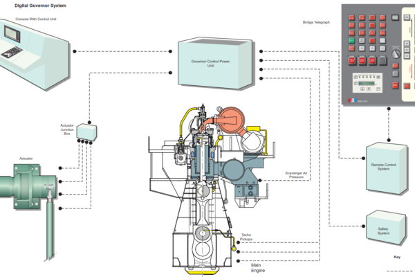
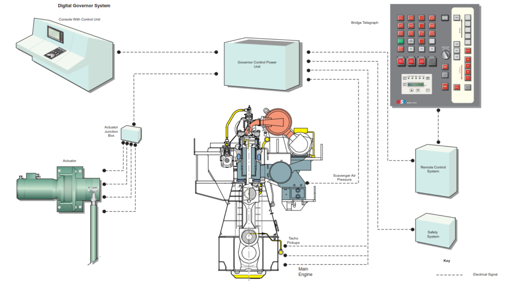
The engine protecting system (EPS) is designed to monitor the ship’s main engine performance and speed, then control the engine protection functions, such as shutdown and slowdown, if the engine’s monitored operations exceed defined limits. The protecting system provides the following control and monitoring facilities:
Control of:
• Emergency stop
• Engine shutdown
• Engine slowdown
Monitoring of:
• Engine speed
• Engine overspeed
• Engine shutdown sensors
• Engine slowdown sensors
• RPM detectors
• Emergency stop pushbuttons
• Emergency stop (auto-stop) solenoid valve
Emergency Shutdown
This function is independent of the engine control system and is available at any time regardless of the control position of the main engine. Visual and audible alarms are issued in the event of a shutdown. When a detector for any of the emergency shutdown parameters detects an abnormality, it energises the emergency shutdown solenoid valve and issues the emergency shutdown signal to the governor which shuts off fuel to the engine. The emergency shutdown parameters are indicated in the table opposite.
It is possible to cancel a shutdown if the SHUT DOWN CANCEL pushbutton is pressed within the specified time period. If the SHUT DOWN CANCEL pushbutton is not pressed the shutdown proceeds and cannot be stopped.
Resetting of the emergency shutdown is undertaken after the fault causing the shutdown has been corrected. Resetting can take place at the following locations.
• The Bridge Control Console by moving the main telegraph manoeuvring transmitter to the STOP position.
• Engine Control Room Console by moving the speed control dial to the STOP position.
• Engine Side Manoeuvring Stand by moving the fuel regulating control to the STOP position.
The shutdown cause indicator in the LCD panel will remain illuminated after the cause has been corrected until the CAUSE RESET pushbutton is pressed at the LCD panel.
Slowdown and Shutdown Functions
| Item | Slowdown | Shutdown |
| LO inlet temperature high | 60C | |
| Piston cooling oil outlet temperature high | 75C | |
| Piston cooling oil outlet no flow | * | |
| Piston cooling oil inlet pressure low | 0.1MPa | |
| Main LO inlet pressure low | 0.1MPa | 0.08MPa |
| Camshaft LO pressure low | 0.1MPa | |
| Turbocharger LO inlet pressure | 0.06MPa | |
| Exhaust valve driving gear LO pressure low | 0.15MPa | |
| Main LO inlet temperature high | 60C | |
| Piston cooling outlet temperature high | 75C | |
| Main bearing outlet LO temperature deviation | +/-7C | |
| Bearing LO outlet temperature high | 70C | |
| Bearing shell temperature high | 70C | |
| Thrust bearing segment temperature high | 75C | 85C |
| Camshaft LO inlet temperature high | 60C | |
| Fresh water cooling inlet manifold pressure low | 0.12MPa | |
| Fresh water cooling outlet/cylinder temperature high | 90oC | |
| Fresh water cooling pressure differential in/out | +/-0.01MPa | |
| Scavenge air box fire detector | 90C | |
| Exhaust gas outlet/cylinder temperature high | 450C | |
| Exhaust gas outlet/cylinder temperature (deviation) | +/-50C | |
| Oil mist in crankcase | * | |
| Engine overspeed | *114 |
Emergency Slowdown
This function is independent of the engine control system and is available at any time under bridge and engine control room control. Visual and audible alarms are issued in the event of a slowdown. Slowdown parameters are given in the table opposite.
Except for the high crankcase oil mist a slowdown may be cancelled by pressing the SLOW DOWN CANCEL pushbutton within a specified time period. If the SLOW DOWN CANCEL pushbutton is not pressed within that time period the slowdown becomes active. In the event of high crankcase oil mist triggering a slowdown this may be cancelled by pressing the OIL MIST SLOW DOWN CANCEL pushbutton within the specified time period.
When a detector for any of the slowdown parameters detects an abnormality the engine reaction differs depending upon the current operating speed.
If the engine operating speed is higher than the slowdown speed level the slowdown signal is sent to the governor to reduce the engine speed to the slowdown level.
If the engine operating speed is lower than the slowdown speed level the slowdown signal is not sent to the governor and the engine speed remains the same.
A slowdown can be reset after the cause of the slowdown has been corrected, resetting taking place at the following locations.
• The Bridge Control Console by moving the main telegraph manoeuvring transmitter to the position below SLOW.
• Engine Control Room Console by moving the speed control dial to the corresponding position below the slowdown level.
The slowdown cause indicator in the LCD panel will remain illuminated after the cause has been corrected until the CAUSE RESET pushbutton is pressed at the LCD panel.
Crash Astern under Control Room Manoeuvring
The crash astern operation can be carried out when the engine is turning in the ahead direction at a speed higher than the normal speed at which reversing of the engine is possible using the control system. In order to prevent a misfire the scavenge air pressure fuel limiter in the governor is cancelled for about 30 seconds. The crash astern procedure is carried out by moving the telegraph receiver knob to the astern position and moving the speed control dial to the START position.
Cancelling of the Fuel Limiter
This function is available under bridge control or engine control room control. The scavenge air pressure fuel limiter is cancelled in the following situations.
• When a repeat start or crash astern is carried out from the bridge control console.
• When the SCAV. LIMIT. CUT OUT pushbutton in the LCD panel is pressed.
• When a crash astern is carried out from the engine control room.
In each of the above cases a signal for cancelling the scavenge air pressure fuel limiter is sent to the governor.
Fuel Cam Abnormal Alarm
If the position of any of the roller guides for the fuel pump cams does not correspond with the position for the ordered rotating direction of the engine a ‘Fuel Cam Abnormal’ alarm is activated on the bridge and in the engine control room if the condition exists for more than 5 seconds.
The situation must be investigated immediately, and the cause of the abnormality corrected.
System Malfunction
A ‘System Failure’ alarm is activated on the bridge and an ‘EPS System Malfunction’ alarm is activated in the engine control room in the event of any of the following abnormalities.
- No.1 rpm pickup abnormal.
- No.2 rpm pickup abnormal.
- RDU abnormal.
- Solenoid valve abnormal. This may be a short or broken circuit in the emergency shutdown solenoid valve.
- Sensor abnormality. This may be an abnormality in the detectors for emergency shutdown or slowdown.
After the cause of the system malfunction has been corrected the alarm is reset by pressing the CAUSE RESET pushbutton in the LCD panel.
Critical Speed Alarm
If the engine runs in the critical speed zone for more than 5 seconds (variable) the ‘Critical Speed’ alarm is activated.
Note: Operation of each of the slowdown and shutdown systems should be tested annually. Checking should be done at a time when normal operation of the ship will not be endangered. Checking is normally done by simulating slowdown and shutdown conditions rather than actually instigating them.