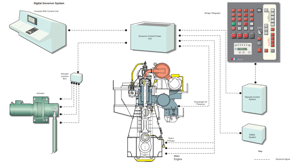
The Electronic Governor System is a control system designed to accurately maintain the output shaft speed of the main propulsion engine to a given order. The governor consists of a microprocessor unit at the engine revolution control part and a fast response electrical servomotor with reduction gear at the actuator part. The servomotor unit is compact and is driven by a brushless electric motor.
In addition to controlling the speed of the engine the electronic governor system provides the following features:
• Indication of control conditions on an LCD panel
• Changing of governor characteristics with protection against incorrect setting of characteristics
• Manual limitation of fuel injection (Manual Limit)
• Confirmation of input and output signals at the governor control unit
• Steady control of the fuel rack (Fuel Mode)
• Direct regulation of the fuel rack from the speed control dial in the control room
• Fixing of the fuel rack position in the event of abnormalities in the governor
Governor Control Unit
This unit is integrated with the engine control system and engine manoeuvring system. For any speed order issued by the engine control or manoeuvring systems the PID calculation is carried out and the fuel control actuator position order (Pθ signal) is issued.
This is matched to the main engine condition and takes into account fuel limiter conditions. The control mode is changed automatically according to the running condition of the main engine.
Servo Panel
This consists of the servo driver, which controls the servomotor, and a number of power supply parts.
Transformer
This supplies the power for the servo-driver.
Governor Actuator
This consists of a brushless servomotor (with resolver and absolute encoder) and the reduction gear. The actuator unit moves the engine’s fuel rack and it is able to be locked in position should a governor malfunction occur. The actuator is protected against overload.
RPM Sensor
This is used to measure the actual engine rotational speed.
PI Transducer
This measures the scavenge air pressure and converts it to a signal (4 – 20mA) for use in the control system for use by the fuel limiter in the event of abnormal scavenge air pressure.
System Features
Self Monitoring
The system hardware and software constantly monitored by the governor control system itself and in the event of any abnormality an alarm ‘System Fail’ is issued in the wheelhouse and an alarm ‘ECS System Malfunction’ is issued in the engine control room. If the abnormality is capable of changing the engine fuel setting, and hence the engine speed, the actuator position (Pθ value) is maintained as it is. In the event of failure of two RS-422 lines between the bridge and engine control room during bridge control, or in the event of failure of speed control dial potentiometer during engine control room control, the main engine speed is maintained as it is.
Fuel Shut Down (Pθ to zero)
In the case of a ‘Stop’ order and ‘Shut Down’ the output shaft of the governor actuator is returned back to zero. (Pθ value becomes zero.)
Start RPM Level
When the air start system operates the governor regulates the engine’s speed to the start rpm level for predetermined periods of time. (Normal Start & Start with scavenge air limiter cut out.) This is undertaken to prevent a misfire and to ensure that the engine starts properly.
Shut Down Level
When the engine is in Auto Slow Down status the upper limit of the control rpm set point is limited to the Slow Down value.
PID Control
PID control is an essential function of the rpm controller as it consists of proportional, integral and differential operations.
Fuel Limit
The following fuel limit functions are provided:
• Scavenge air limiter by means of the scavenge air pressure
• Fuel limiter by means of the rpm control
• Manual maximum fuel limiter by means of a setting parameter
When a particular limiter is activated the relevant display on the LCD panel is highlighted.
Control Mode
There are two control modes, RPM mode and Fuel mode; either can be selected but normally RPM mode is selected during times of engine speed change such as manoeuvring and Fuel mode is selected when the engine is operating under steady speed conditions.
RPM mode is used to control engine speed according to the desired rpm within a specified deviation. Essentially it is a constant speed mode.
Fuel mode maintains a constant fuel setting by locking the actuator position (Pθ value). In the event of either of the following conditions rpm mode is automatically changed to fuel mode:
• The selected rpm is in the range of the navigation speed zone.
• The selected rpm is fixed.
• Deviation of the engine rpm is within the specified range for more than 10 seconds.
When the rpm deviation in Fuel Mode is higher than a predetermined value the control mode is automatically returned to rpm mode.
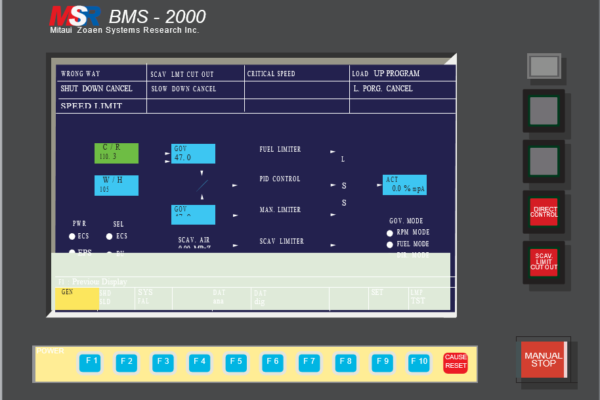
Govenor Status Display
Governor Bypass (Direct Control)
If necessary the engine fuel pump control rack may be manually controlled via the speed control dial when engine room control is activated. Direct control is possible when the DIRECT CONTROL pushbutton in the LCD panel in the control room console panel is pressed.
Status Display and Data Display
Governor information is displayed on the LCD panel in the engine control room console. The controlled status of the engine can be checked at the display and various parameters (digital values) of the RPM controller can be set or changed.
Operation Test
Governor digital and analogue input/output signals can be checked using the test procedure at the LCD panel. Testing must be carried out when the engine is stopping and the test procedure is ineffective whilst the engine is starting or running.
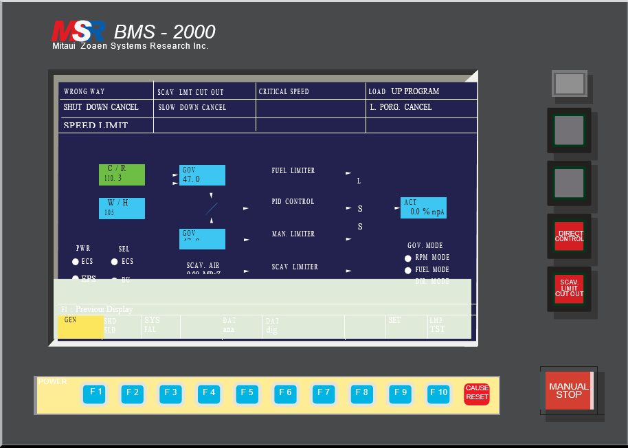
Operation of the bridge manoeuvring system
The bridge manoeuvring system LCD panel is used for the governor and other systems of the engine control and manoeuvring systems. To the right of the display there are three illuminated pushbuttons:
• SCAVENGE LIMIT CUT OUT
• DIRECT CONTROL of the engine from the control room
• MANUAL STOP of the engine
The LCD can display pictures in one of the following groups:
• General
• Shut Down and Slow Down cause elements
• System failure (EPS and ECS) cause elements
• Analogue input/output data and control figures
• Digital input data
• Test screens
• Parameter setting screens
In the Governor Test screen the following parameters are displayed:
• Governor Output
• Governor feedback (display only)
• Set Point P1 for analogue output (display only)
• Set Point P2 for analogue output (display only)
• Governor Output (Analogue output for display only)
RPM Detecting Unit
The RPM detecting unit consists of four pickup sensors positioned close to the toothed rim on the engine flywheel. The detecting unit detects the pulses from the flywheel teeth and converts this into an engine rpm. Green LEDs on the detector panel are illuminated when the sensors are operating correctly; if the associated red LED is illuminated it means that that sensor is defective.
Servo Unit Panel
No changes should be made to the servo unit without the authority of the Chief Engineer and without prior consultation with the engine manoeuvring system manual.
The governor servo display operating unit permits setting of user parameters, H-parameters and servo adjustment values via the operating keys. The operating unit has a five digit display which shows the operating state and alarms.
The MODE key is pressed to move through status display, adjustment checks and user parameter areas.
In each of these areas the UP and DOWN arrow keys are pressed in order to select the menus. When a parameter or function has been selected the UP and DOWN arrow keys are pressed in order to change the numeric value of a parameter when setting.
The SEL key is the data set digit feed key and this shifts display digits to the left.
The ENTER key confirms set values and acts as a alarm reset pushbutton.
If it necessary to make changes to the servo settings the engine manoeuvring system manual must be consulted first as faulty setting can result in serious engine damage.
Governor Actuator
The servomotor is a sealed unit and must not be tampered with.
The servomotor should be checked daily for vibration or noise or for any signs of damage.
Annually the servomotor wiring should be visually checked and the insulation resistance should be checked.
The reduction gearing of the servo unit is initially packed with grease and no attention is required for five years when the gearing should be checked and new grease applied.