The burner is of the rotary cup type and so does not require any atomising steam or air supply. Control air is needed for valve actuation and purging and an electrical supply is required to operate the rotary cup drive motor. Combustion air is supplied by means of an electrically driven forced draught fan. The air supply is regulated by means of dampers. The forced draught fan is situated at the wind box and it supplies air for the primary fan which is an integrated part of the burner. Primary air represents about 7% of the total air supplied, the remaining 93% being secondary air from the forced draught fan. The secondary air for combustion is supplied to the wind box and is directed into the flame by means of vanes.
Atomisation of the fuel oil film leaving the rotary cup is by means of the primary air which is supplied at a pressure of 12-15kPa.
Correct control of the secondary air is essential to efficient combustion throughout the entire turn-down range of the burner. Draught control is performed by means of a secondary air damper connected to the compound regulator by a rod linkage. The fuel oil compound regulator is the final control element which meters out fuel oil and combustion air to the burner.
The rate of fuel flow is controlled in a linear manner by a rotary valve in the compound regulator. A cam is used to regulate the air damper control lever to compensate for the non-linear operation of the secondary air control damper.
Ignition of the burner is by means of a diesel oil igniter inserted through the wind box and air register. The ignition burner lance and nozzle are automatically purged with air when the ignition period has ended.
The turn-down range for the burner is 4:1. A low fire start interlock prevents flashing up on high firing rate.
Water Level Control
Feed water supply to the boiler is handled by a single element control system. It is designed to maintain the boiler water level and provide an alarm and safety shut down should the level not stay within set limits. A transmitter is mounted on the boiler which sends a signal to the controller, which in turn regulates the opening of the feed water control valve.
The feed water control valve has an electro-pneumatic valve positioner for automatic operation. The feed pump(s) operate continuously and the feed control valve regulates the amount of water directed to the boiler, depending upon the current water level. A set of direct feed valves is provided to be used in the event of failure of the feed water controller.
The safety system consists of two independent means of shutting off the fuel supply to the burner if the water level in the boiler falls to an unacceptably low level. A separate low level float switch shuts off the fuel supply when the water level falls to a low value. Limit switches located on the boiler control panel, are connected to the differential pressure transmitter which operates the feed water controller.
These provide for the following:
• Shut off the fuel supply to the burner at low water level
• A high/low water level alarm
• Stop the feed water pump at too high a water level
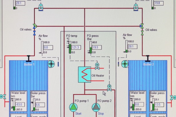
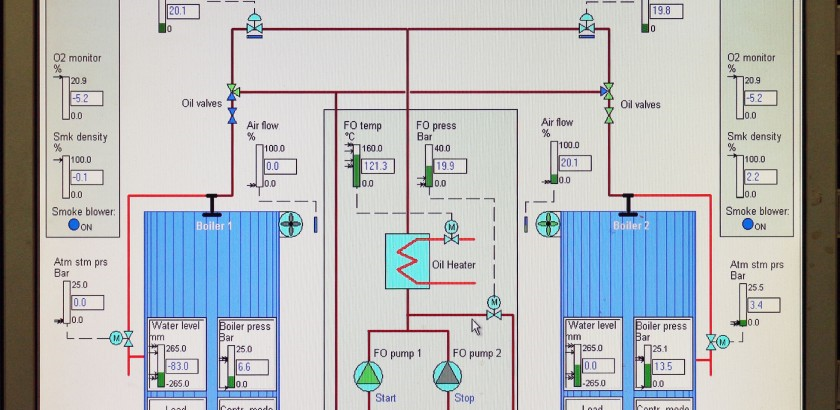
The Boiler Control Panel
The boiler control panel provides operation, control and interlock devices required for the running of both the oil fired boilers and the exhaust gas economiser. This control panel performs the automatic and manual operation of the boiler plant and it gives an alarm to warn the operator if an abnormality occurs during operation.
There are two control panel sections for the oil fired boilers control and one for the fuel oil pressure/temperature control. a common section for the feed water system. These sections are interlinked. The boiler feed water regulator operates continuously when the boiler is operating and acts to open or close the automatic boiler feed water supply valve in response to the level of water in the boiler.
The boiler control system stops the boiler in an emergency mode, by immediately shutting down the fuel oil supply to the boiler, if such an abnormality should be too serious to continue running any longer.
Master Boiler Control Panel
This panel contains the system power supply unit and controller for the burner control and automatic process control plus various relay units.
The system has alarms and trips which provide for safe operation of the boiler. The alarms bring an abnormality in operation to the notice of the engineer and a trip initiates a shutdown. The alarm and control panel is provided with a lamp test pushbutton which enables the lamps to be tested; this should be carried out daily in order to enable failed indicator lamps to be detected and replaced.
Burner Control System
This system controls the remote, manual and automatic operations of the burner in the boiler. The unit contains a sequence control, which operates the furnace purge, pilot burner and the automatic operation of the burner piston valve.
The burner sequence control unit is designed for control and supervision of the oil burner in automatic operation. The control unit is connected to a photo cell and in normal operation it controls the flame supervision circuit.
Note: The burner sequence control unit has no function when the oil burner is running in manual mode.
During start-up the control unit operates the oil burner in a pre-selected start- up sequence. In the event of fault during start up or in normal operation, the fuel supply is instantaneously interrupted, and the sequence control unit stops the oil burner.
The control programme sends the necessary input signals to the control section of the control unit and the flame supervision circuit. If the required input signals are not present, the control unit interrupts the start-up sequence and initiates a lockout where this is required by the system safety regulations.
Operating Procedure
• The START command is given by the pressure switch of the installation.
• Start-up sequence.
• The burner is in operation, according to the control commands of the load controller.
• Controlled shutdown through the pressure switch.
• The sequence mechanism runs into the start position for the post purge.
Note: During burner off periods the flame supervision circuit is under voltage in order to carry out the flame detector and extraneous light test.
Prerequisites for Burner Start-Up
• Burner is not interlocked in the lockout position.
• Air damper is closed.
• The control contacts for the fuel valves CLOSED must be in the closed position
• The normally closed contact for the air pressure monitor must be closed
Start-Up Sequence
Start Command by the Pressure Switch
a) The pressure switch closes and the sequence mechanism starts to run. At the same time the fan motor is started on prepurge.
b) After a preset time has elapsed the fan motor is activated in prepurge and post-purge mode.
c) On completion of a further time interval the control command to open the air damper is given. During the running time of the actuator, the sequence mechanism stops. Only after the air damper has fully opened does the sequence mechanism continue to run.
d) Prepurge time with the fully opened air damper. During the prepurge time the correct functioning of the flame supervision circuit is tested. The control unit goes into the lockout position in case of an incorrect function of the relay.
e) After completion of the prepurge time, the control unit drives the air damper into the low flame position. During the damper running time the sequence mechanism stops again.
f) Pre-ignition time. The process of ignition is started with air and fuel being supplied in the correct proportion and the pilot burner operated.
g) Safety time. This delay period allows for ignition of the main burner and the photocell to detect the flame before the end of the safety time. The flame must be continuously present otherwise the control unit initiates a lockout and interlocks itself in the lockout position.
h) Second safety time. On completion of the second safety time the main burner must have been ignited by the pilot burner.
i) End of the start-up programme. After a preset time interval has elapsed, the load controller is released. This ends the start up sequence of the control unit. The sequence mechanism switches itself off, either immediately or after a few idle steps, i.e. steps without change of the contact positions, depending on the times.
Burner Operation
During burner operation the load controller drives the air damper into nominal load or low flame position, depending on the demand for heat. The release of the nominal load is carried out by the auxiliary switch in the air damper actuator.
Controlled Shutdown
a) The fuel valves are closed immediately; at the same time the sequence mechanism starts again.
b) Post-purge time. Shortly after the start of the post-purge time the air damper is driven into the MIN position.
c) The complete closing of the damper starts shortly before the post purge time has elapsed. This is initiated by a control signal which also remains under voltage during the following burner- off period.
d) Permissible after-burn time. During this time the flame supervision circuit may still receive a flame signal without initiating burner lockout.
End of control program.
e) On completion of the post-purge time the detector and extraneous light test starts again, as soon as the sequence mechanism has reset the control contacts into the start position.
f) During the burner off period a faulty flame signal of a few seconds only initiates lockout. Short ignition pulses of the UV- tube, eg. caused by radiation, do not initiate burner lockout.
The boiler is normally operated on HFO with MDO being used for the igniter. MDO may be used in the main burner. The burner is not purged after the burning of MDO is completed or in the event of an emergency stop.
Procedure for Automatic Burner Operation
The description below assumes that the fuel system is ready for operation with heated HFO available.
a) Check the fuel and burner system for leaks and ensure that the boiler is ready for operation.
b) Turn the burner control panel main power switch to the ON position and check that the fuel supply valves are open.
c) Check all panel lamps by pressing the LAMP TEST pushbuttons.
d) Check that the water level in the boiler is within acceptable limits with one feed pump selected as the operating pump and the other as the standby pump.
e) Select one auxiliary boiler burner FO pump as the operating pump and the other as the standby pump.
f) Turn the Control Voltage switch to the ON position and the Oil Heating switch to the ON position. If MDO is being burned the Oil Heater switch must be in the OFF position and the Thermostat Bypass switch is set to the ON position.
g) Turn the Boiler Modulating mode switch to the AUTO position.
h) Select automatic operation by turning the key operated Burner
Operation Mode switch to the AUTO position.
i) Turn the Burner Auto switch to the ON position; the burner will start and stop automatically by a signal from the start/stop pressure switch. The start up sequence and flame supervision (by means of the auto flame scanner) are controlled by the burner sequence controller.
When the start-up sequence is completed the burner will be modulated according to the setting of the burner modulation mode switch. There are two burner modulation modes, auto and manual.
Auto Modulation: The Burner Modulation mode switch is in the AUTO position and the burner load is controlled automatically by the load controller.
In an emergency, the control system shuts off the fuel supply to the burner for the boiler protection. An emergency stop pushbutton is provided at the boiler control panel to enable the operator to stop the burner operating should that be necessary. The boiler control panels provide visual indication of existing alarm conditions by means of indicator lamps. These lamps must be tested daily by pressing the LAMP TEST pushbutton.
Manual Operation
The manual operation system allows for firing of the boiler, in the event of faults in the automatic sequence control or components of safety monitoring equipment.
Procedure for Changing to Manual Operation
a) Check the fuel and burner system for leaks and ensure that the boiler is ready for operation.
b) Turn the burner control panel main power switch to the ON position and check that the fuel supply valves are open. Check all panel lamps by pressing the LAMP TEST pushbuttons.
c) Check that the water level in the boiler is within acceptable limits with one feed pump selected as the operating pump and the other as the standby pump.
d) Select one auxiliary boiler burner FO pump as the operating pump and the other as the standby pump.
e) Turn the Control Voltage switch to the ON position and the Oil Heating switch to the ON position. If MDO is being burned the oil heater switch must be in the OFF position and the thermostat bypass switch is set to the ON position.
f) If the boiler is cold the oil flow control switch must be turned to the MANU/LOW position.
g) Turn the Burner Operation switch to the MANU position and, after the Ignition Ready lamp is illuminated, press the IGNITION MANUAL switch.
h) Ignition of the pilot burner normally takes about 3 seconds but if ignition of the pilot burner has not occurred after 5 seconds turn the Burner Operation switch to the OFF position and investigate the cause of the ignition failure.
WARNING
It is essential that the boiler furnace be purged correctly in order to reduce the risk of furnace explosion.
i) Ensure that the furnace is purged correctly for the required period of time; the forced draught fan must be run at full speed and the furnace dampers should be fully open.
j) Check that the boiler fuel oil pressure and temperature are correct.
k) After ignition of the pilot burner takes place and the furnace has been properly purged, at the manual operation box, press the Manual Oil Solenoid Valve pushbutton and the Manual Ignition pushbutton together. Check visually that a stable main flame is established when there is a stable main flame release both pushbuttons.
Note: The manual operation box is located at the burner and not at the control panel.
l) The burner will remain firing; the oil valve and flame will be supervised by the manual flame scanner.
m) If no flame is established when the ignition and oil valve pushbuttons are released, the start-up sequence must be repeated from step h) above.
n) Burner firing is stopped by turning the Oil Solenoid Valve manual switch to the OFF position.
Note: If the burner is started on MDO the change to HFO firing must take place when the temperature of the HFO is correct. When changing to HFO firing the Oil Heater switch must be turned to the ON position and the Thermostat Bypass switch turned to the OFF position.
CAUTION
In manual operation mode the safety interlocks are reduced to:
• Too low water level
• High steam pressure
• Burner swing out
• Overload combustion air fan and burner motor
• Flame failure
It is essential that the boiler is constantly supervised by a competent engineer when operating in manual mode.
Smoke Density Monitor
A smoke density monitor is fitted in the flue uptake of each boiler and operates using a light source and a photoelectric sensor. Should there be a reduction in amount of light, from the light source, falling on the detector this indicates an increase in smoke in the flue gas and an alarm is triggered. The indicator operates in the range Ringelmann 0 to 5.
The smoke density monitor must be zeroed before use and a check must be made on the zeroing and operating range at monthly intervals; this is done as follows.
a) Ensure that the boiler is shut down and only clean air is passing through the uptake.
b) Switch on the smoke density indicator power source and ensure that the ON-OFF switch at the indicator is in the ON position.
c) Obscure the light beam so that no light is falling on the detector; turn the ‘Zero Adjust’ dial so that the indicator pointer is reading 5 on the Ringelmann gauge.
d) Ensure that full light falls on the detector and turn the ‘Zero Adjust’ dial so that the indicator pointer is reading 0.
The alarm activation point is set by turning the ‘Alarm Point’ dial to the Ringelmann number at which the alarm should be triggered. There is a time delay between the high smoke density being monitored and the alarm activation, the delay is set at 40 seconds as default. This delay is needed in order to prevent activation of the smoke density alarm when flashing up the boiler. The alarm delay can be set at any time between 0 – 120 seconds by turning the timer dial on the printed circuit board inside the control box. The time delay may be tested by obscuring the light beam with a card and timing the interval before the alarm is activated. Operation of the smoke detector should be tested each week by obscuring the light beam with a piece