The Gauging system
Most of the terminals these days demand that a closed gauging / sampling system be followed on all tankers at their terminals. This means that the tanker must be able to gauge or sample the cargo in her tanks manually or automatically without opening her cargo tanks to the atmosphere. In this chapter we will describe such systems. Ship personnel must understand that the below mentioned systems may differ from their ship’s system and the ship’s operation manuals and other literature must be consulted prior operating it.
Automatic gauging systems
Below mentioned are two most common systems in use, viz.
- Float gauge system
- Radar system.
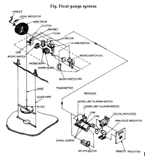
Float gauge system
There are four types of float gauges used commonly on tankers.
- One system uses a stainless steel wire to suspend the float and the wire is wound on a drum, which is connected, to an electric motor. The motor winds the wire when there is slack in the wire and pays out when the tension increases i.e. the torque required is provided by the electric motor.
- In the second type the float is suspended by a tape and the tape is wound on a drum, which is held under tension by a coiled spring i.e. the torque is provided by the spring.
- The third system uses a combination of spring and electric motor.
- The fourth system uses an air motor.
In each of the above systems, the float moves up or down along two guide wires which are fastened at the top of the tank and to the bottom and are held tight by means of springs. These guide wires prevent the float from moving sideways with the liquid. The float is partially buoyant i.e. it cannot float independently and the tension in wire / tape provides the extra buoyancy by means of a motor or a spring.
The motor or the spring generates a constant torque in the direction of winding up. The motor or the spring does not have sufficient torque to support the weight of the float by itself and requires the inherent buoyancy of the float to support the float on the surface on the liquid. Thus when the level of the liquid rises, the tension on the wire / tape reduces and the motor or the spring picks up the slack on the wire / tape.
When the liquid level decreases, the float moves with the liquid and this increases the tension on the motor / spring which then pays out to reduce the tension. The depth of the float from the reference point on top of the tank is indicated locally and remotely (if installed).
After the completion of cargo operations, the float is wound up with a key or the unit may have a switch to wind up the float and then the float is secured on top inside the housing on deck.
To put the unit in operation the float has to be unlocked and lowered to the surface of the liquid. The local reading and the remote readings should be compared with readings obtained from a UTI (Electronic tape, also known as the ‘Ullage, Temperature Interface) and adjustment made. The equipment is described later in the chapter. It is better to compare the reading with the reading given by the manufacturer and make adjustments as required when the float is housed and when the tank is empty.
Precautions to be taken:
Spring type float gauge
- In this type the complete arrangement works mechanically without involvement of any electrical parts. Electricity is used only to display the reading in a remote location. The mechanical parts need lubrication as per manufacturer’s instructions.
- The float has to be lowered carefully by using the handle, till it reaches the surface of the liquid.
- When winding up the tape, it should be done slowly and the lock should be engaged properly.
- The drum revolutions caused by the movement of the surface of the liquid are relayed to the local gauge by means of gears. These gears have to be kept well lubricated.
Electric motor type float gauge:
- Since electric power is used the equipment should be completely intrinsically safe.
- The lubricating oil required should be maintained as per manufacturer’s instructions.
- De waxing of the movable parts in the deck unit may be required to remove the cargo deposits.
Radar type gauge
The system is made up of the following parts,
- Transmitters
- Level unit
- Workstation
The system can be used to monitor cargo tank levels, ballast tank levels, high and high-high level alarms and for feeding the ‘on line’ cargo monitor (loadicator).
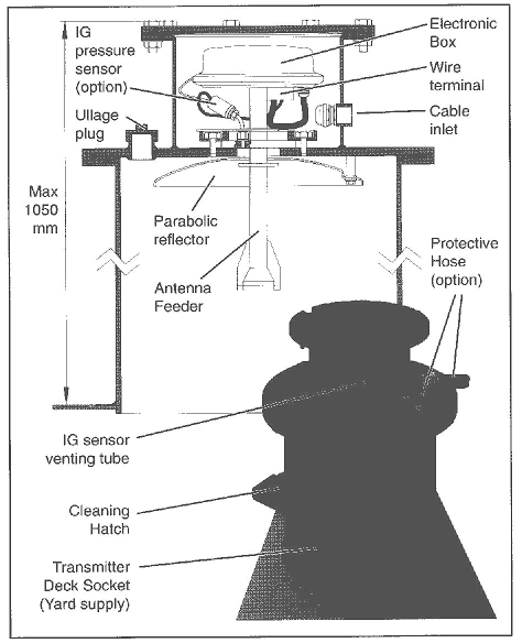
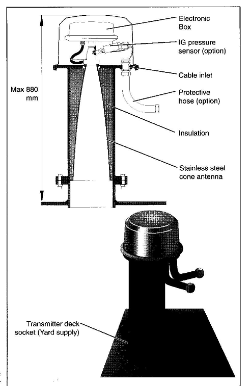
The transmitters measure the distance to the product surface using a continuous radar signal. They have an electronic box for generating and processing the radar signals. There are two types of transmitters in use viz. Parabolic antenna and Cone antenna.
The level unit houses the electronics for processing the signals from the transmitters, for calculations of the tank parameters, and for communication with the workstation.
The ullage can be displayed locally and / or at the remote workstation.
The advantages of the tank radar system are:
- Since there are no moving parts there is no question of any part getting stuck and hence highly reliable.
- The nature of the cargo, the gases in the tanks do not affect the reliability of the system.
- The only part located in the tank is the antenna and it can be easily changed with closed tank conditions.
Principle of operation
The transmitter emits radar waves towards the surface of the product and it is reflected by the surface of the liquid and these reflected radar waves are received and processed.
The frequency of the transmitted signal decreases over a time period. The incoming signal is compared with the outgoing signal and the difference between these two signals is calculated. This difference is directly proportional to the distance and this distance is indicated as the ullage on the display unit.
This is called FMCW (frequency modulated continuous wave) method.
The signal is filtered using a digitally controlled analog filter, to filter out the disturbance.
Health Hazard
There is no health hazard associated with the use of the radar gauge, as the power density close to the antenna is only 0.001 mW/cm2
The power decreases away from the antenna and hence there is no danger from the radar waves to the ships crew even if they are in the tank when the unit is operational.
Below are diagrams of the two types of antenna in use.
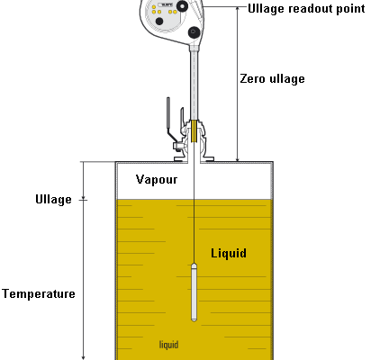
Manual system of gauging a tank
Gauging can also be done using portable UTI (Ullage, temperature, interface) gauges. These equipment needs to be fitted on top a ullage port and the readings read out on the tape in case of ullage / interface or digital display in case of a temperature.
The unit as shown in the figure below consists of a:
- Display unit which houses the LCD display, buzzer, crank, tape cleaner, window, reading index, and window wiper. This display unit is fitted over a storage drum capable of reeling in and reeling out a tape along with its sensor by means of a crank handle provided. The unit is powered by a battery inside the display unit which doesn’t consume a large amount of power. A continuous tone of the buzzer indicates a weak battery and needs to be replaced in a safe area.
- A storage tube connects the base of the display unit to the ullage port by means of a quick connector.
- Graduated tape
- Sensor
The tape
The TEFZEL coated tape provides 3 main functions
- It holds the sensor
- It has graduations (in centimetres and inches), which make it possible to determine the distance between the end of the sensor and the reading index.
- The tape contains two wires for transmitting the signal and power between the display unit and the probe. The steel tape itself acts as a grounding wire between the probe tube and the display unit.
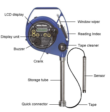
The sensor (probe)
It consists of a stainless steel tube terminated by a plastic head which is an integral part of the tube. The probe includes an ultrasonic liquid level sensor, a temperature sensor and a conductivity electrode. The sensor is connected to the tape by means of an oil tight connector and does not require any adjustment for sensitivity for ullage / interface measurement or temperature calibration.
Ullage detection
The ullage detector consists of two piezo ceramic plates and electronic circuits inside the sensor. When the sensor head is immersed in a non-conductive liquid (oil , petroleum) the emitted ultra sonic signal is detected by the receiver, coded and sent to the instrument which activates the buzzer with a continuous beep.
Interface detection
The measurement of conductivity between an active and grounded electrode is the basic principle of this detection. When the liquid is conductive (water) the ullage sensor detects the presence of the liquid and the conductivity of the electrodes, the circuits modulate the coded signal to generate an intermittent beep.
Temperature measurement
The sensing element is a platinum resistance temperature detector element. The element is located in the temperature electrode, which is fitted in a heat transfer compound paste to reduce the response time. The signal is digitised and after all the errors have been compensated and corrected by the micro processor in the sensor it is sent to the display unit for the user to read it off.
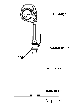
For using this instrument in the closed measurement mode it needs to be installed on top of a ball valve arrangement fitted onto the cargo tank. The quick connector is provided at the base of the storage tube, which fits onto the top of the valve which in turn is fitted on a standpipe welded to the cargo tank at a predetermined location on deck. This valve is known as the vapour control valve. The valve is normally always kept shut. It needs to be opened only when the instrument is fitted on top of the valve and a measurement needs to be taken.
This instrument can also be used without the vapour control valve in which case the quick connecter of the instrument is fitted directly on top of a standpipe without a vapour control valve.
Using the instrument
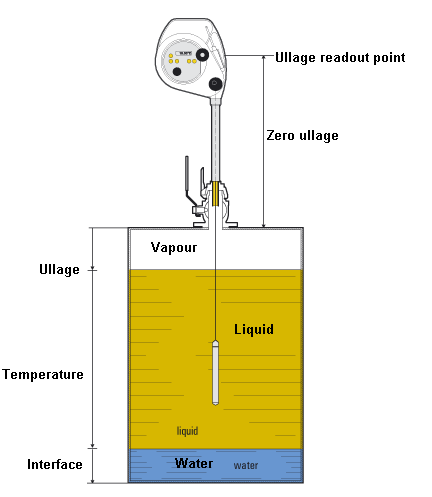
Having fitted the instrument in place the vapour control valve is opened and the crank is turned to gently lower the tape along with its sensor into the tank. When the sensor touches the liquid surface of oil it generates a continuous beep. When this happens the tape reading must be noted on the reading index. This indicates the ullage of the tank.
If a beep becomes or changes to intermittent when lowering the tape further it indicates the presence of water and the level at which this happens can be read on the ‘reading index’ of the instrument.
The reading on the reading index must read the maximum ullage of the tank when it touches the tank bottom and must read zero when the level of the sensor is exactly at the top of the tank. A correction must be applied if this does not happen. Each tape and the standpipe location point must be approved and calibrated to show a proper reading of ullage. The corrections are also recorded in the appropriate tank calibration tables and on the instrument.
Temperature measurements are obtained on the digital display by using a selector switch on the instrument, which indicates the temperature of the liquid at the position of the sensor. This is useful when temperature of the liquid is needed for various levels. Remember to keep the sensor at one place for at least 2 minutes before recording the temperature.
The tape must be wound up and retracted once the measurements have been taken and the vapour control valve shut before disengaging the instrument from the quick connector of the vapour control valve.
Care must be taken to ensure that the tape is completely would up before closing the valve so as to avoid damage to the tape. Some instruments have a protective metal sleeve fitted above the sensor to prevent the closure of the vapour control valve while the tape is still inside the tank; this sleeve automatically retracts once the sensor enters the storage tube and allows the valve to be closed without damaging the fragile tape.
Sampling and density measuring
Sampling
Sampling of cargo is a routine to be followed to keep evidence and record of the quality of cargo loaded in the tank. Earlier days (still done at some ports) sampling was carried out by using a bottom weighted brass bottle sampler with a cork stopper tied to a string. The bottle itself was lowered in to the tank with its stopper closed, taking sufficient care to keep adequate slack on the string. A firm pull on the string by the sampling person at the desired level allowed the oil to fill up inside the bottle. This method can no longer be used with the closed loading / discharge systems in place therefore the need for a modern sampler which enables their use in restricted or closed gas tight version to allow sampling of liquids, which presents a Fire, Health or Air pollution hazards.
The equipment looks more or less like the manual gauging equipment where instead of a sensor a sampling bottle is attached to the end of a graduated tape coiled on a reel. A crank is provided to lower and hoist the tape and the level can be read off on the reading index. The sampler can be connected to the vapour control valve fitted atop a sampling port using a quick connector.
Provision is made to drain the sample obtained into a suitable container by means of a valve provided at the base of the equipment when the bottle reaches the top of the sampler.
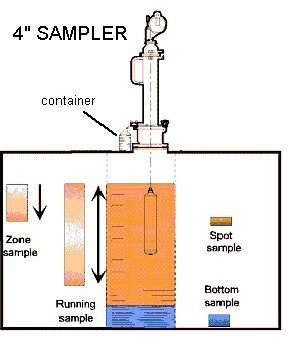
The different types of sampling procedures are possible with the above equipment.
Zone sampling: Where the liquid in the sampling bottle represents a sample of the layer located near the level required. e.g. say around 5 meters of the ullage in the tank.
Spot sampling: Where the liquid in the sampling bottle represents a sample located exactly at the level required. e.g. say exactly at 10 meters of ullage in the tank.
Bottom sample where the bottle opens when it strikes the bottom of the tank and closes when lifted thereby giving a bottom sample.
Running sample where the liquid in the bottle represents a core sample through all the levels of the bulk liquid.
It may be required to sample the cargo using the above techniques. These depend upon the requirements of the charterers and surveyor. Running sampling and bottom sampling methods are the most commonly used.
Density measurement
It is not a common shipboard practice as the measurement of density of oil cargoes is done in controlled conditions ashore by laboratory specially equipped for the purpose. This data may be given in terms of API. However if required the density measurement is carried out on board using glass hydrometers specially constructed for this purpose. These are bottom weighted (to keep them vertical when afloat) glass bulbs with a long graduated stem on which densities are read out. When immersed into a liquid the amount of sinkage depends upon the density of the liquid at that temperature. The more the hydrometer sinks the lesser the density. All densities must be observed at the corresponding temperature.
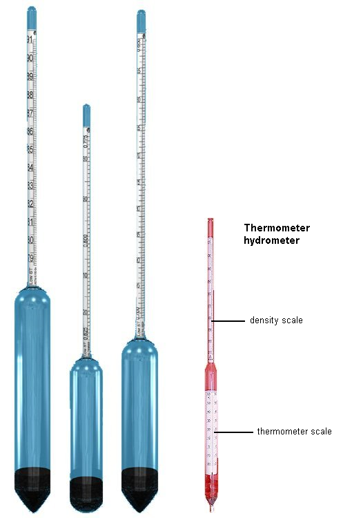
Hydrometers may also have a built in thermometer to obtain the temperature at which the density is observed. These are called thermohydrometers.
However if an ordinary hydrometer is used a separate thermometer needs to be immersed in the same liquid at the same time and the temperature obtained at that density reading by the hydrometer.
Vessels do keep a set of hydrometers or thermo hydrometers covering a range of densities for example:
0.610 to 0.700
0.680 to 0.770
0.750 to 0.840
0.820 to 0.910
0.890 to 0.990
0.980 to 1.100