General
This system is provided to improve the efficiency of stripping work. It can perform complete stripping work by the cargo oil pump (hereinafter called “pump”) alone.
The features of this system are as follows:
1) since most of stripping work is automated” pump operation is very easy.
2) since stripping work can be done by large capacity pumps alone instead of conventional small capacity reciprocating strip pumps” unloading time can be reduced.
Basic Principle and Actions
The basic principle of this system is to automatically prevent the suction of gas into the pump. By doing so” the completion of stripping by the pump alone becomes possible.
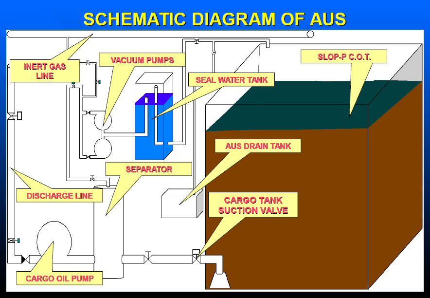
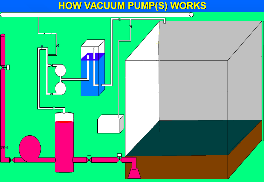
1) Removal of gas from pump suction pipe.The gas sucked in from the suction bell & mouth and the cargo oil vapour produced in the suction pipe are separated from the cargo oil in the separator and gathers at the upper part. These gases are extracted by the vacuum pump out of the top of the separator.
2) Discharge control valve (hereinafter called “discharge valve”) for preventing pump from sucking in gas.
3) When a large volume of gas comes into the separator in the stripping stage” its liquid level becomes very low.
4) When a large volume of gas is sucked into the pump” pumping becomes impossible.In order to prevent this condition” the discharge valve is controlled to the degree corresponding to the liquid level in the separator (hereinafter called ”separator level”) and the pump discharge flow is adjusted.
5)When the separator level falls excessively” the discharge valve is throttled to decrease the suckingamount of gas from the bell&mouth and it prevents the suction of gas into the pump.
6) When the separator level falls below the minimum set value ” the discharge valve is fully closed.
Function Of Components
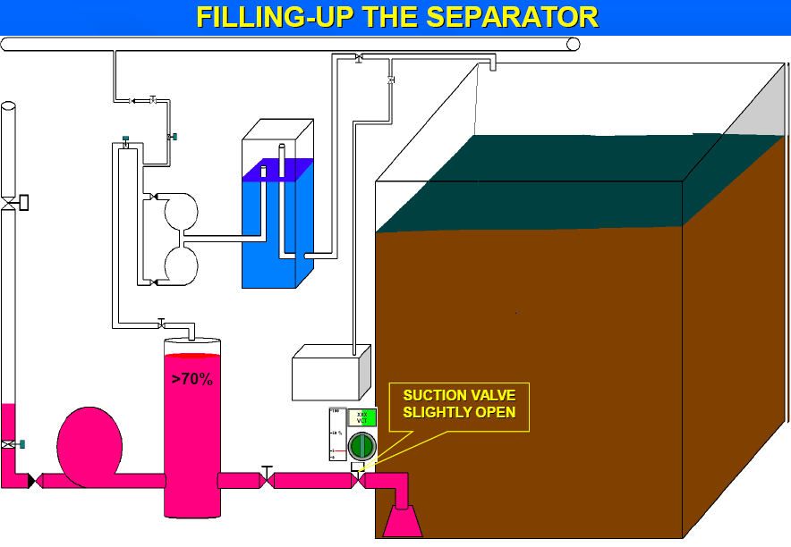
1) Separator :
This is tank to separate the gas sucked in through the bell & mouth and the cargo oil vapour produced in the suction line from cargo oil. The separated gas is extracted by the vacuum pump through the gas extraction pipe connected to the top of the separator.
2) Level transmitter :
This is consistent with main body (differential pressure measuring portion and pneumatic signal converting portion) and low-high pressure detectors (diaphragm seal type).Pressure detector is connected with main body via lead(filled with sealed liquid) and low-high pressure detectors are fitted to upper and lower part of separator. Static pressure (basic pressure) of sealed liquid of lead and static pressure of separator liquid level which is transmitted from high pressure side diaphragm are acting to the main body. The gas pressure in the separator acts evenly on both sides of the low-high pressure detectors and thus its effect is cancelled” so that the main body only measures the differential pressure of both static pressures. This measured differential pressure is converted into pneumatic signal as a separator level and transmitted to cargo control console.
3) Discharge valve :
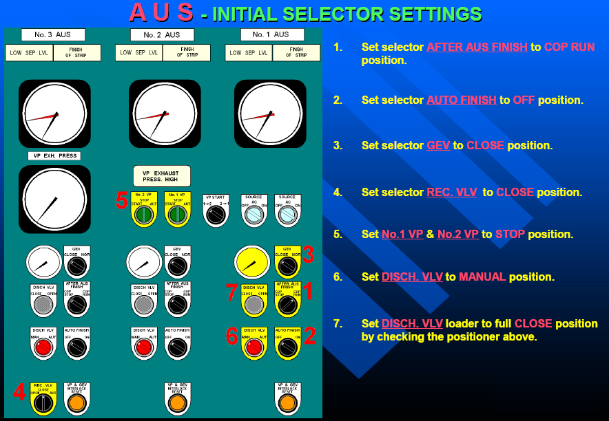
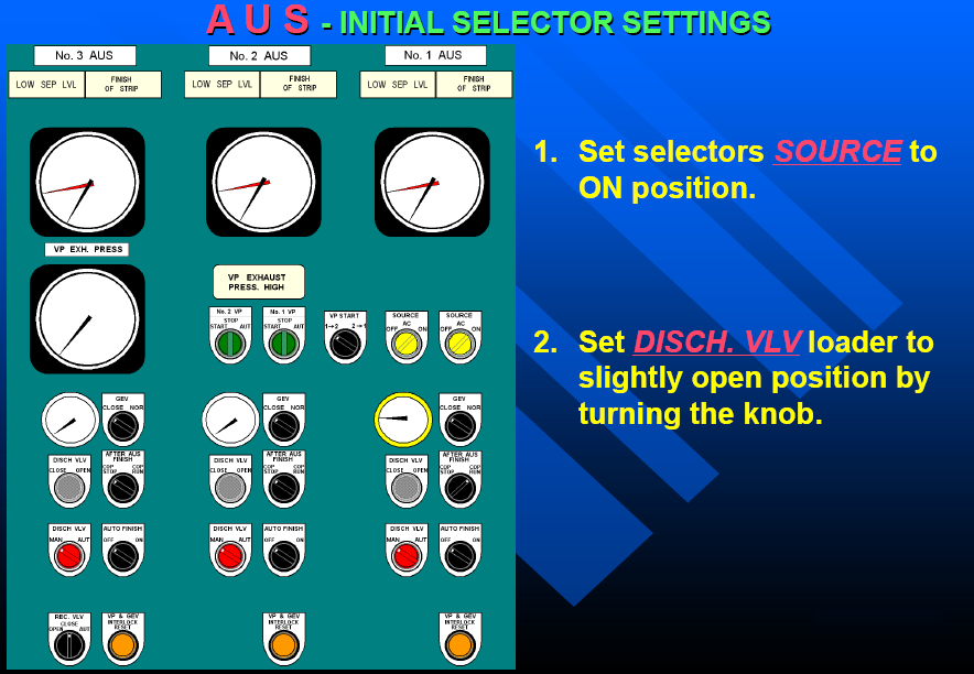
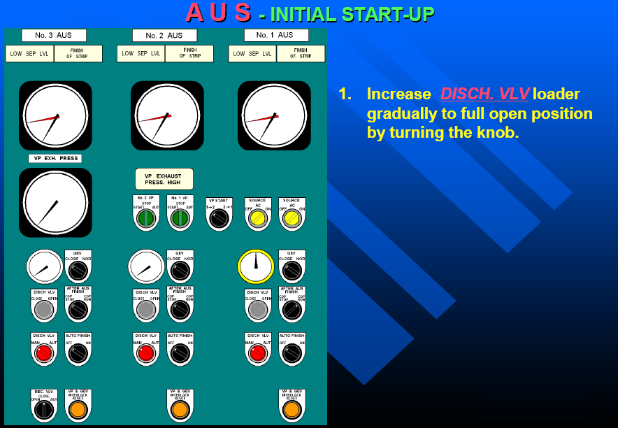
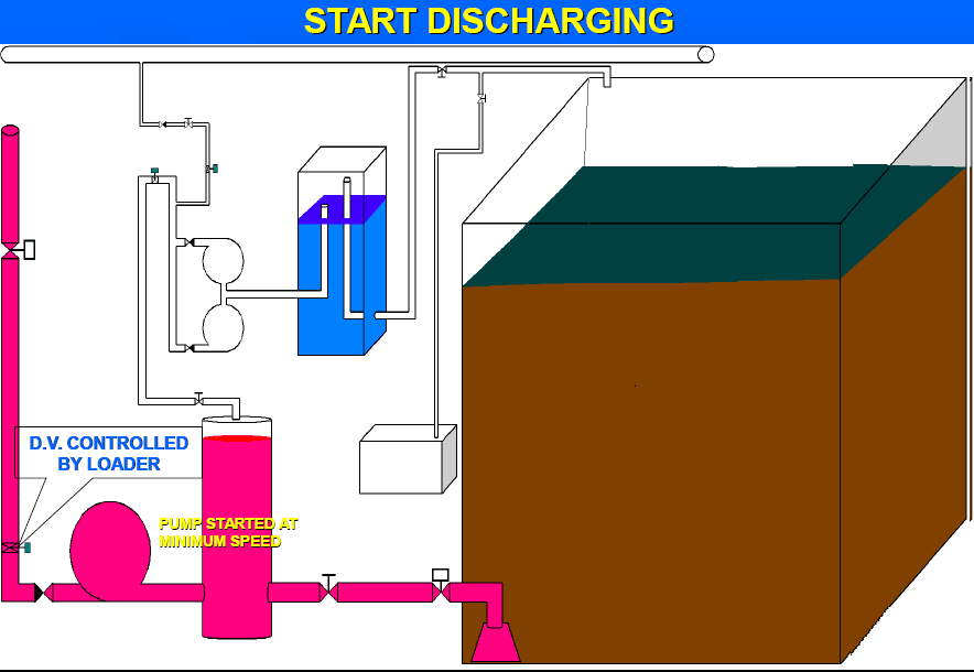
This is of butterfly type valve driven by pneumatic cylinder and controls the pump discharge capacity.This valve is remote & controlled by the valve opening signal (automatic control or manual control signal)from 0-1 selector.
(4) Valve position transmitter:-
This transmitter” which is installed on the discharge valve ” converts the opening of discharge valve into pneumatic signal and transmits it to the valve position gauge on the cargo control console.
(5) Vacuum pump:-
This is of horizontal water ring type. This is driven by the motor through the intermediate shaft which passes through the bulkhead and extracts the gas separated in the separator and discharge it to the slop tank.This pump is automatically started and stopped by the pressure switches which are operated by the pneumatic signal from the level transmitter.By means of the control switch” manual start and stop can be also made.
(6) Sealing water tank:-
This is tank to separate the gas from sealing water which is discharged from vacuum pump and to hold the sealing water necessary for the vacuum pump function.
(7)Function valve:-
This is of screw & down check angle valve fitted on the suction flange of vacuum pump. When the vacuum pump stops this valve closes to prevent sealing water and gas from flowing back to the gas extraction line.
(8) Gas extraction valve:-
This is of pneumatically operated piston type installed on the gas extraction line and is opened and closed by the solenoid valve control led through the pressure switch.This valve is in the same system as the automatic start and stop circuit of vacuum pump and opens when separator level is less than 50% and closes when it returns to 100% or more.
(9) A/M selector:-
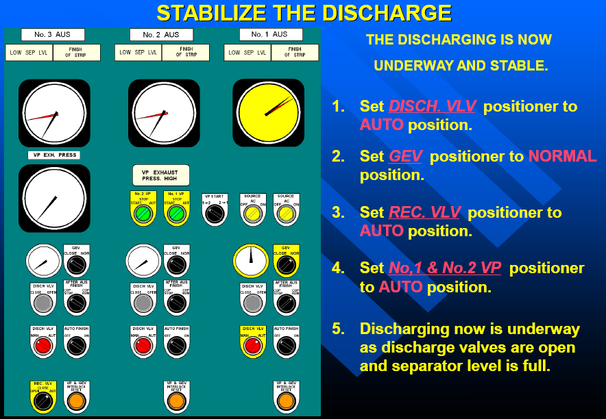
This is used to change over the discharge valve to automatic or manual control. By setting the A/M selector at “Manual”” it can be remotely operated by manual loader to get any opening.
(10) Solenoid valve:-
The valve is controlled by the pressure switches operated through the pneumatic signal from the level transmitter” and opens and closes the gas extraction valve by changing over the gas extraction valve operating pneumatic line.
(11)Positioner:-
This is fitted on the discharge valve and it corresponds the discharge valve opening to the opening signal from the A/M selector.

(12)Booster relay:-
The booster relay” which are provided on the open side and shut side of pneumatic cylinder respectively”change over the loading pneumatic line of pneumatic cylinder through the pilot signal transmitted from the positioner to open or close the discharge valve.
(13)Lock valve:-
This is fitted on the discharge valve and it locks the discharge valve opening in case of the driving air pressure drops abnormally low.
(14)Speed controller:-
The speed controllers” which are provided on the open side and shut side of pneumatic cylinder respectively” controls the opening-closing speed of the discharge valve.
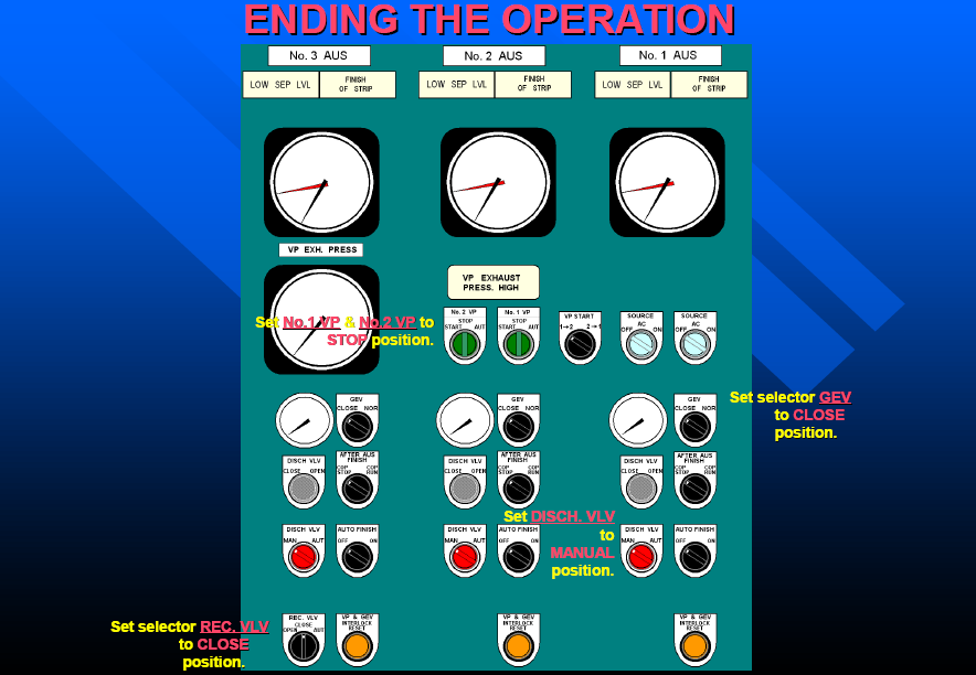
Operating procedure of system (AUS)
(1) While the liquid level in the cargo oil tank (hereinafter called tank level) is high, this system does not work.
(2) As the tank level falls” the suction pressure also falls and approaches the vapour pressure of the pumping liquid.In this case part of the pumping liquid will turn to vapour and accumulates in the top of the separator and as a result the separator level begins to fall.
(3) When the separator level falls down to below 50% the pressure switch is actuated by a pneumatic signal from the level transmitter and the vacuum pump starts. At the same time the gas extraction valve opens and the discharge valve is throttled.
(4) When the separator level recovers above 70% the gas extraction valve closes and 10 seconds later the vacuum pump stops and the discharge valve opens.
(5) Every time the vapour of pumping liquid accumulates in the separator top the above mentioned conditions (3) and (4) are repeated and thus the unloading work is advanced while the suction of gases by the pump is being prevented.
(6) When the tank level further falls (e.g. when the bottom longitudinals of the hull appear above the oil surface) eddy begins to occur around the bellmouth. Soon when the bottom of the depression of this eddy (gas column) reaches the bottom face of the bellmouth gas begins to be sucked into the bellmouth.
(7) The gas sucked in is separated from the pumping liquid in the separator and accumulates in its top lowering the separator level. Hereupon the action described in (3) and (4) above is repeated.
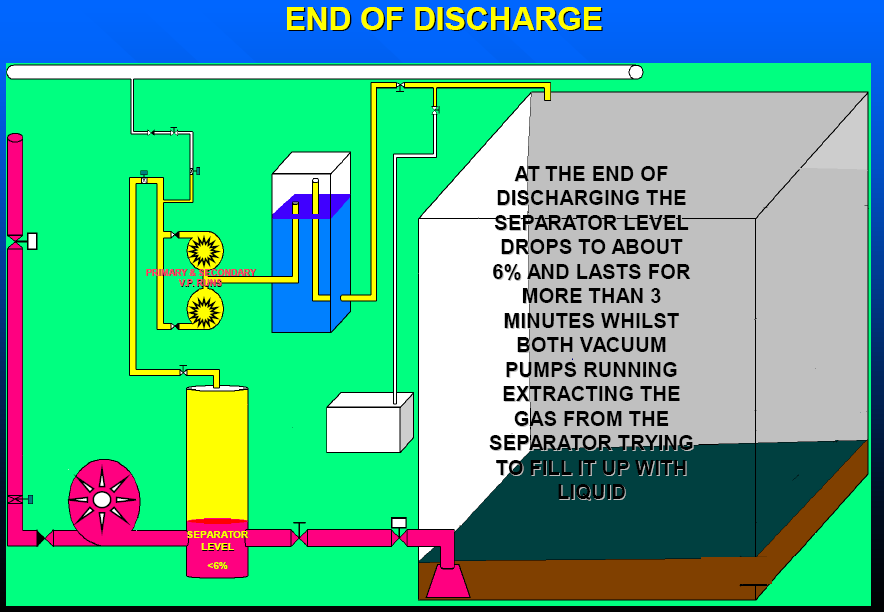
(8) When the tank level further falls the liquid surface around the bellmouth comes to wave violently and a large volume of gas comes to be sucked in directly from the bottom face of the bellmouth. Under such condition even though the vacuum pumps are operated” the separator level falls to a great extent.
(9) As a result the signal air pressure of the level transmitter falls excessively” greatly reducing the opening degree of the discharge valve” namely the pump discharge flow decreases considerably.In consequence” the speed of the pumping liquid flowing into the bellmouth decreases and the wave motion of the liquid surface around it becomes small.Thus the volume of the gas sucked into the bellmouth decreases.
(10) When the volume of the gas sucked in becomes less than the extraction capacity of the vacuum pump the separator level begins to rise. At the same time the discharge valve opens gradually and the pump discharge flow begins to increase.
Thank you very much for such clear explanation.