Types of Valves
You have by now understood the functions of a valve. These act as controls and allow or stop flow of any material. In the study of these valves, it is necessary to understand:
- The mechanism which controls the flow,
- Operation of the mechanism,
- Maintenance needs,
- Common problems that are normally experienced in operation.
All ships have some type of valve systems to control the flow of fresh water, ballast water, pumping out of bilges, transferring of bunkers and for pressurising the hydraulic systems for various control operations. They come in all sizes and shapes and can be operated by almost all energy sources available on the ship including, manual labour. On tankers they assume even more importance as they help orderly loading and discharge of cargoes.
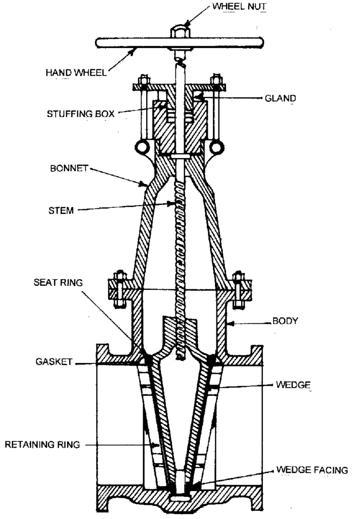
Gate valve
In this type of valve, a gate (or sluice) is raised or lowered by turning the spindle, which passes through the gate. This spindle is threaded and these threads engage in the nut, which is inserted in a slot at the top of the gate. By turning the hand wheel, the spindle is turned and thus the gate moves up and down.
The gate is tapered towards the bottom and this helps in giving a better seal. The gate slides up and down in a slot and in the open position the gate is lifted into the bonnet and hence offers no resistance to the flow of the liquid.
The gate valve is quite reliable and does not normally leak. If a solid object gets stuck between the gate and body of the valve, it may not be able to close fully, thus allowing the liquid to flow through. This is overcome by opening and closing the valve a few times.
These valves are normally found in the cargo system as manifold valves, sea chest valves, master valves, isolation valves and tank valves
If this type of valve gets damaged then it has to be replaced, as repairing it requires the face of the seat to be built up and then lapped or the gate to be built up and lapped and this is a laborious and time consuming process. Even after these repairs the valve may still allow leakage.
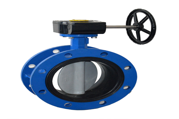
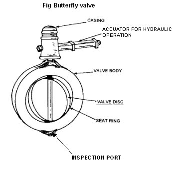
Butterfly valve
This valve is so called because it has a flap, which is perpendicular to the flow of liquid in closed position. In the open position, it is parallel to the flow of the liquid. The spindle passing through the flap of the valve is connected by a gear arrangement to a wheel or directly to a handle.
Turning the wheel or the handle changes the angle of the flap with respect to the direction of flow of liquid. The valve body has a seat ring, which is essentially a steel ring with a neoprene seat and the flap seals against this seat when in the closed position.
The valve has an inspection port at the bottom which can be opened to check if the valve is opening / closing properly. The spindle may fracture if the valve is operated rapidly against a strong flow of the liquid.
The neoprene on the seat ring tends to get damaged over a period due to frequent opening / closing of the valve and due to solid objects that may be in the liquid. The valve has to be removed with the flap in the closed position to replace the seat ring. After the ‘Allen’ bolts holding the seat ring are removed the flap is slowly turned in the open direction which dislodges the seat ring. The new seat ring is installed with the flap in 5 – 10% open position. This is done so that after the seat ring is installed and the flap is closed the seat ring fits tightly in its position.
If the spindle is damaged then the valve has to be changed but it is possible to change the spindle if a spare is carried on board. Every ship with butterfly valves normally carries spare seat rings for all sizes needed. These valves are all-purpose valves and are used extensively on the ship. They are however not used for overboard connections for sea chest as they are not as strong as gate valves and globe valves. Also since there is a rubber seat ring in the butterfly valve it is susceptible to damage. In case of gate and globe valves, since there are no rubber parts, they are preferred.
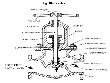
Globe valve
This is a valve with a bulbous body and it has a seat on which valve disc rests to prevent flow of liquid.
These valves may be of non-return type wherein the wings guide the disk. The disk is connected to the spindle, which can be raised or lowered on the seat.
These valves can be used to change the direction of the flow of liquid by 90º or they can be in the same axis as the flow of liquid. They can be of the non-return type (allow flow in one direction only) or allow the flow of liquid in both directions. In both type of valves the preferred direction of flow is with the liquid entering the valve from the bottom and coming out on top as shown in the figure. These valves are normally used as sea chest valves, on the tank cleaning line and on the fire line.
In case of a Screw down non-return valve (SDNRV), when the valve is opened, the pressure of the stem is withdrawn from the disc and the disc can move upwards in case there is pressure from the bottom, but if the pressure decreases / stops, the disc will move downwards and seal against the seat. If there is pressure from top of the disc, the disc will prevent the flow of liquid. Thus the valve becomes a non-return valve.
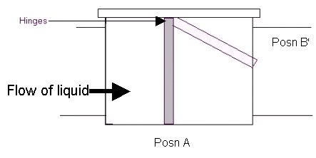
Non return valve
A non-return valve consists of a flap which is hinged on top and which is free to move in one direction only. Thus when the liquid flows in the direction of the flap the flap opens (Posn. B) and the liquid can pass through but as soon as the flow stops, the flap returns to the closed position due to the weight of the flap, which brings it to the closed (Vertical) position. At the vertical position (Posn A), a stopper stops the flap from moving to the other side. If flow starts in the opposite direction the flap acts as a barrier as it cannot open in that direction. This valve is used in the cargo system to prevent flow of the cargo in the wrong direction e.g. flow of the cargo to the tank through the pump.
Fig – Non return valve
HYDRAULIC SYSTEM FOR VALVE OPERATION
This system provides for the remote operation of valves connected to the system. Thus system can operate butterfly valves, gate valves and globe valves with the help of actuators fitted on the valve.
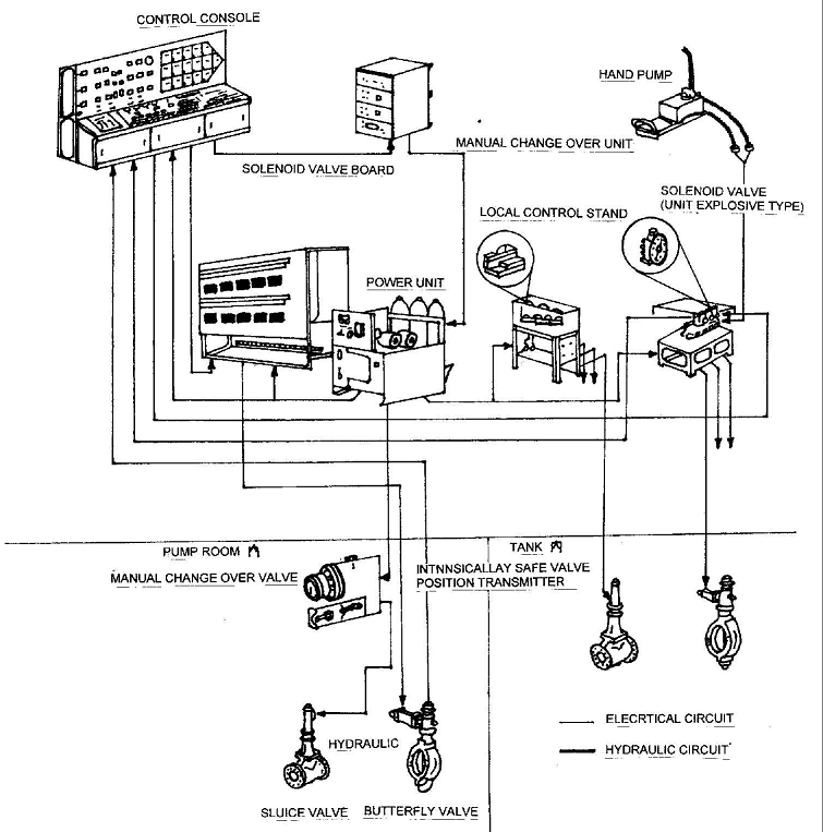
The Power unit consists of Oil reservoir, electric motors, hydraulic pumps, relief valve, solenoid valve, pressure switch, check valve, accumulator, low level alarm and filter.
The oil reservoir has a capacity of about 500 litres and two motor driven pumps are installed. (One of the pumps is set as primary and the other as reserve). Both the hydraulic pumps transfer the oil from the reservoir through the check valves into the accumulator. The accumulator has a low-pressure alarm and a high-pressure alarm. The low-pressure alarm light shall be lit when the system is started. When the pressure rises above the low oil pressure level, the pressure switch releases the alarm and the light on the control panel indicating low oil pressure shall be extinguished. When the pressure reaches the working pressure set on the equipment, the power to the motor of the reserve pump is switched off and pumps stops pumping. The primary pump keeps pumping until the pressure reaches the ‘high pressure limit’.
At the high-pressure limit the relief valve opens and the oil pumped by the primary pump flows back to the reservoir. The pump keeps running in the unloaded condition. When the pressure in the system falls due to operation of valves or leakage or such other cause, the relief valve closes and the pump starts pumping in the loaded condition to build up the pressure. If the primary pump cannot compensate the pressure fall then at a preset pressure the reserve pump motor starts and maintains the pressure. Under normal conditions if no valves were operated, the primary pump would run in the unloaded condition for about 10 minutes.
The pumps are normally of the Vane or Gear type. These types of pumps are positive displacement pumps but they cannot pump large quantity of oil. The grade of oil used is as specified by the manufacturer and the same grade should be used. It is normal practise to carry at least 1000 litres of spare hydraulic oil of that grade. This is for a contingency if there is a major leakage whereby lot of oil could be lost in a cargo tank or on deck.
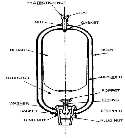
The accumulator is a sealed container and has a synthetic rubber bladder filled with nitrogen gas inside. In order to avoid frequent cutting on and off of the pump, the gas in the bladder is compressed when the pump is running and as the pressure drops due to valve operation, the gas compensates for pressure drops by expanding. When the oil is pumped into the container the bladder gets pressurised and compressed. When the oil is being used the pressure in the container falls, the gas in the bladder expands and pressure in the container is maintained. The gas expands and at a pre-set pressure the pump cuts in. the pump runs in loaded condition and builds pressure in the system until the pressure reaches the set pressure at which the solenoid activates the relief valve if there is no load.
Similar process works in the hydrophore system, which keeps fresh water under pressure all the time.
Practical operation of the hydraulic system:
Close the bypass valve before switching on the power for the system. The bypass valve connects the discharge line from the pump, to the return line from the deck and when opened it allows the oil under pressure in the system to return to the reservoir. This valve should be kept closed when the system is operational and be opened only if there is a leak in the system whereby it becomes necessary to reduce the hydraulic pressure immediately. When a leak is detected, the pumps should be stopped, by pass valve opened and the pressure in the system is released.
When switching on the power, the operator decides which pump is to be primary and which standby. This is done so that both the pumps are used alternately and one pump does not get worn out due to continuous use while the other suffers due to non use.
It is a good practise to check the level of oil in the reservoir regularly and a record should be maintained of any replenishment done after the system has started. It should be noted that any replenishment should be done with the knowledge of the chief officer and the replenishment should bring the level of oil to the level at which the pumps were started. If the reservoir is topped up while the system is in operation, the reservoir will overflow after the oil returns to the reservoir if it is already full.
If the oil level falls during valve operation, then such valve should be identified so that operation of that valve could be avoided and the hydraulic line leading to the valve attended to at the first possible opportunity.
The spare hydraulic oil drums should be marked and only the correct grade of oil kept in the hydraulic room to replenish the reservoir.
When the switch on the control panel for a particular valve is operated, it sends a signal to the solenoid on deck, which operates to allow the oil to flow in the appropriate direction to operate the valve.
In case of emergency, the solenoid has an arrangement to connect a manual hydraulic pump to operate the valve in case of failure of the hydraulic system. The isolation valve on the hydraulic box housing the solenoid should be shut so that the pressure is applied within the lines in the affected area. Adjust the speed at which the valve operates.