
CHECKS PRIOR USING ECDIS FOR APPRAISAL AND PASSAGE PLANNING
Following checks should be carried out by the Navigating Officer while carrying out passage planning on ECDIS:
- Not all sea areas are covered by ENC charts. The electronic chart coverage for the voyage must be adequate and all relevant charts must be fully corrected. For areas covered by ENC, it is mandatory that they be used instead of RNC. If RNCs are to be used, a set of updated paper charts for those areas shall be made available onboard.
- Check local requirements of coastal states that may require carriage of additional publications or local charts.
- Check that electronic charts have been updated to the most recent version and chart permit licenses have been bought.
- The vessel’s controlling operational parameters (maximum draft, air draft, turning data, minimum under keel clearance required, ‘look ahead’ distance etc.) should be entered.
- The GPS position system should be set to WGS 84 datum.
- The alarm functions of the ECDIS should be fully operational; they will alert the operator of any danger exposed in good time during the voyage.
- Carry out ‘Route Check’ to ensure that vessel will not encounter navigational hazards on the planned route. A visual check of all ENCs being used for the voyage at the best scale must be carried out.
- When planning new way points and courses, always use the largest scale possible so all features of the chart can be readily identified.
- Ensure that the plan takes into account sufficient cross-track error (XTE) to accommodate any deviations for collision avoidance or currents.
- Ensure adequate values are input for safety contour and depth alarms.
- Check that tidal information is up to date and correct.
- CATZOC should be considered for depth while checking the available UKC in the passage.
- Date dependent features which may arise on ENC at a future date must be considered.
USE OF ECDIS FOR ROUTE PLANNING
ECDIS provides many benefits for route planning; a few of which are:
- A quick and easy to select saved routes and prepare new ones.
- Routes can be easily modified with the use of the planning graphic tool.
- Measurements and calculations are much easier.
However, planning a safe route requires experience, time and adequate familiarity with the general principles of ECDIS and navigators should be aware of the following:
- Check Route Function: The navigating officer should make use of the check route function after passage planning to ensure that vessel will not encounter navigational hazards on the planned route. These hazards would be mainly pertaining to grounding dangers, crossing TSS line / boundary and user defined alarms.
- Visual checks at compilation scale prior approving the plan must be carried out. This will assist in overcoming the issues of missed out information due to inappropriate scaling/ display/ SCAMIN of ENC.
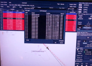
- On coastal passages / shallow waters , ENCs will be populated with many area related cautions. These may result in numerous warnings being generated during the planning stage leading to missing out of critical item alert. It is important that all warnings / alarms are carefully checked.
- Information on an ENC along the route requires to be accessed in full. The procedure for the complete access to information will depend on the make/ model of the ECDIS and is given in the manufacturer’s manual.
- Navigators should be aware that a geometrically incorrect alarm will be displayed if the distance between two waypoints is very short or if the turn is very sharp. In such a case, the radius and/ or speed should be adjusted to clear the alarm.
- Proper appraisal of collecting information from the relevant publications needs to be carried out prior plotting route on the ENC.
- The finally approved route should then be appropriately saved and also copied to the back-up system.
- Speed Plan: The planned speed for the leg, which will always be at or below the safe speed, after considering the proximity of navigational hazards along the route, the depth of water and the manoeuvring characteristics of the vessel.
- Turn Information: This can usually be entered by rate of turn or radius. The system will normally calculate one from the other one, and display both parameters using the planned speed for the leg.
- CATZOC information to be considered during route planning.
Markings on the Chart:

The electronic chart should be marked with:
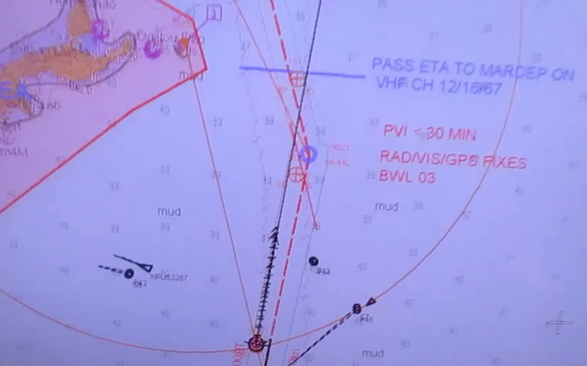
- Prominent navigation and radar marks
- Parallel index lines (not from floating objects unless they have been first checked for position)
- No go areas
- Landfall targets and lights
- Clearing lines and bearings, safe distance off
- Transits, heading marks and leading lines
- Significant tides or current
- Safe Speed and necessary speed alterations
- Call Master Point/ Changes in Machinery Status and notices for main engine / Anchor clearance
- Minimum under keel clearance
- Crossing and high density traffic areas
- Contingency plans / Abort positions
- VTS and reporting points
- Any other user defined notifications as considered necessary
EXECUTION AND MONITORING
- For change of watch, “Changing over the Watch While Underway checklist to be complied with for carrying out checks on ECDIS.
- Check that the display has been set-up properly prior to sailing, otherwise important information may not be displayed. There are generally three default settings of the layers of an ENC i.e. Base, Standard and Other. The ENCs should normally be in full access mode. In case the text information clutters the other chart information, the text layer may be disabled.
- Day / Night Settings: The display should be set up to meet the appropriate conditions on the bridge. There are three main viewing modes available: daytime, dusk and nighttime. CAUTION – When using night / dusk settings, background colours get altered and shoals / other dangers may not be readily apparent. Until good orientation is achieved, it is advisable to switch to Day settings occasionally.
- Always use ENC on the best scale possible to avoid crucial information being auto filtered and subsequently not being displayed. e. When executing a route, progress against the original plan must be constantly monitored.
- Marking and highlighting of electronic charts should be carried out in a similar way to paper charts. Such marking should identify radar conspicuous targets, no-go areas, parallel index lines, transit marks, clearing bearings, etc.
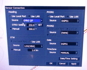
- Data input from the gyro compass, speed log, echo sounder and other electronic equipment to the ECDIS should be periodically monitored to ensure accuracy using ‘Sensor Monitor’ window.
- The look-ahead facility should warn of any hazards ahead off screen but do not rely on it; always use the zoom and scrolling facility to look ahead. Look-ahead range time range for route monitoring is an operator specified parameter. It is important that this time or distance is carefully set to meet the particular circumstances. If set too long it will create numerous alerts that may distract the navigator.
- Navigating officers must not become over-reliant on ECDIS. Frequent checks should be made of the ECDIS position fixing system (normally GPS) by the use of other means to crosscheck and determine vessel’s position.
Such checks should include:
- Parallel indexing and use of clearing bearings.
- Visual cross bearings.
- Use of radar to check the accuracy of the charted position.
- Comparison of signal to noise ratio of the GPS system in use ( HDOP value)
Traditional forms of position fixing should never be overlooked or replaced when using ECDIS; these can include but are not limited to:
- Visual bearings
- Radar ranges and bearings using variable range markers (VRMs) and electronic bearing lines (EBL)
- Transit bearings and clearing ranges
- Running fixes
- Fixing by a line of soundings
- Horizontal sextant angles (HSAs)
- Positions by celestial means (sextant)
- If ARPA overlay is used, targets not acquired by the ARPA will not appear on the ECDIS. Similarly targets not fitted with AIS will not appear on ECDIS.
Therefore, ECDIS should not be used as primary means of collision avoidance.
CRITICAL ALARMS AND ALARM SETTING GUIDANCE
When using ENCs, an alert will be given when charted hazards enter the safety domain, even if the hazard is not visible on the displayed portion of the ENC. The alarms listed below should be kept activated at all times.
Alarms are to be set by the navigating officer at the time of passage planning and once the Master has reviewed the passage / alarm settings, they should be locked where such a facility is available.
The alert will be an alarm or indication, depending on the circumstances and user settings.
During passage, if any of the below alarm is received, O.O.W. should immediately inform Master:
1. Crossing Safety Contours / Depth
- There are generally three contour settings available to the user for highlighting available depth. The contours are differentiated by colours and if a guard zone touches the safety contour it will give an alarm. The contour will be selected only for that value for which a contour exists on the ENC. If any other value is selected, it will then select the next available contour.
i. Safety Contour: This is a user entered depth that ideally coincides with the contours, giving an adequate safety allowance for the dynamic draft of the vessel.
ii. Deep Contour: This is user entered depth that will affect the appearance of spot soundings. It uses just two colours. All areas deeper than safety contour are shown in white/ black (depending upon day/night settings); all areas shallower than the safety contour are shown in blue.
iii. Shallow Contour: The navigator emphasizes deep and shallow areas by use of contrast colour using this mode. Vessels should not be entering in this contour.
- Safety Depth: This function is primarily used for the route check and an alarm will be generated upon encountering shallower depth in look-ahead area. The spot soundings below the specified values will appear bold.
My Company ECDIS Safety Settings :-
Minimum Settings: Setting should be based on vessel’s dynamic draft.
Dynamic draft = Present maximum static draft + All allowances ( Squat + Sinkage due to Density Allowance for Sea State + Heel Correction + Seasonal variation + other allowances)
Shallow Contour >= Dynamic draft
Safety Contour >= Dynamic draft + minimum net UKC requirement for that area + 2 meters (safety margin)
Safety Depth >= Dynamic draft + minimum net UKC requirement for that area Safety Height: Air draft of the vessel + 1 meter.
Deep Contour >= 50 meters
Area with special conditions
An alarm or indication, as set by the user, will be given if, within a specified time or distance, own ship would cross the boundary of a geographic area for which special condition exist such as Traffic Separation Zone, Caution area, anchorage area, Particularly Sensitive Sea Area, Military practice area.
Minimum Settings: To be set at time greater than Position Fixing Interval (PFI) for particular leg of the passage plan.
- Deviation from route
An alarm will be given if the specified cross track limit for deviation from the planned route is exceeded.
Minimum Settings: To be determined by the Master after reviewing the passage for proximity of navigational hazards. - Positioning system failure
Navigating officers should be aware of the non-reliability of the GPS input to ECDIS. An error message will be displayed if the GPS signal is lost stating that ‘DR positioning is being used’. - Approach to critical point
An alarm will be given by the ECDIS when the ship reaches a specified time or distance, set by the mariner, in advance of a critical point on the planned route.
Minimum Settings: To be set at time greater than PFI for particular leg of the passage plan. - Different geodetic datum
From data contained within the RNC, ECDIS equipment automatically performs the datum conversion from WGS84 or else it will provide a continuous indication that the referencing can not be performed. If the datum between RCS and position fixing system is different, it will cause an alarm to be generated to alert the navigating officer. However it is recommended to keep GPS in WGS 84 datum all the time. - ECDIS failure
Similar to other electronic navigational equipment, ECDIS can fail, either outright or in a way that can give misleading information. The navigator shall transfer navigation to the back-up system. - Approach to mariner entered feature, e.g. area, line
An indication will be given if, continuing on its present course and speed, over a specified time or distance set by the mariner, own ship will pass closer than a user specified distance from a danger (for example obstruction, wreck, rock or an aid-to-navigation) that is shallower than the mariner’s safety contour or an aid-to-navigation.
Minimum Settings: To be determined by the Master after reviewing subject passage for proximity of hazards.
Anti Grounding Cone
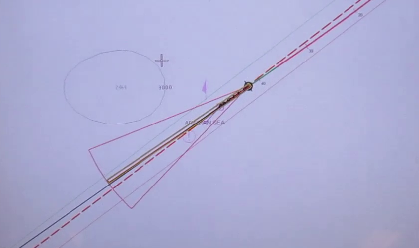
The anti grounding cone safety frame covers the area that will be used by ECDIS for generation of anti grounding alarm, area alert or navigational alarm based on the chart data analysis or the user set safety parameters.
Safety frame of the Anti-grounding tool may be of below types:
Box shape (As Danger detection Vector)
Cone shape (As Danger detection Sector)
The size of anti-grounding tool will depend upon manufacturer of ECDIS system in use. Within the option provided by the manufacturer, Master should decide the optimum setting of size for particular passage or leg of voyage basis size, manoeuvrability and speed of the vessel, proximity of navigational hazards, position plotting frequency, etc.
CROSSING SAFETY CONTOURS/ DEPTH/ HEIGHT
a. The following 4 settings are available to the user for highlighting available depth.
i. Safety Contour
ii. Safety Depth
iii. Deep Contour
iv. Shallow Contour
i. Safety Contour: This is a user entered value based on the vessels dynamic draft + adequate safety allowance. The ECDIS software will choose the next available deeper depth contour and shade the areas of the chart below this contour depth in blue.
e.g.: If the safety contour value is set to 6m, the ECDIS will take the next deeper contour on that ENC (for example 10m). The colour of chart shade below 10m contour will change to blue.
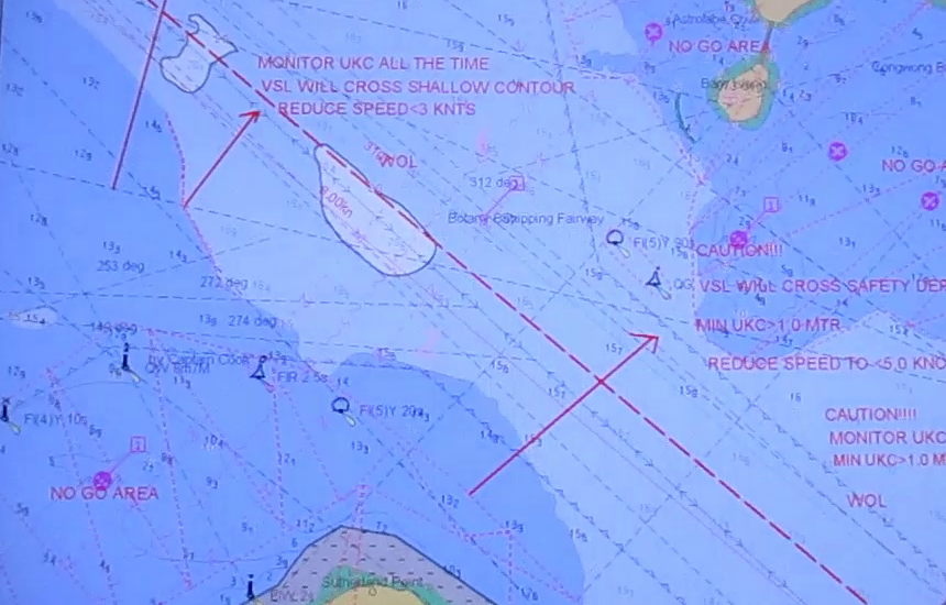
Whilst in the route monitoring mode, an alarm will be activated when the look ahead watch vector crosses the safety contour:
- This gives the mariner advance warning that the ship is approaching potentially dangerous shallow waters.
- O.O.W. should check and assess the distance and time available to reach till adjacent artificial safety contour
- It should be confirmed that the crossing safety contour was as expected and discussed during passage plan meeting
- O.O.W. should inform Master.
- Any note such as tidal window to cross that area should be checked and verified for compliance.
- It should be confirmed that alarm feature is on for adjacent artificial safety contour and vessel is navigating clear from this line.
ii. Safety Depth: Most ENC cells contain same standard range of depth contours that are shown on paper charts (2m, 5m, 10m, 20m, 50m etc). This limits the effectiveness of Safety Contour feature.
As explained in the example for Safety contour, the ECDIS will highlight waters between 6m and 10m also as potentially dangerous.
In order to provide improved visualization, Safety depth setting is provided in the ECDIS. Any sounding with a value equal to or less than the Safety Depth value entered by the operator will be displayed in bold to make them prominent.
Accordingly the value of Safety depth should be same as the value of Safety contour setting.
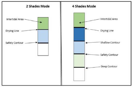
To allow more elaborate distinction of the depth areas, ECDIS has an option of choosing 2 colour shading or 4 colour shading. By default the 2 color shading will be set in the ECDIS.
In the 2 shade mode, all depth area with soundings less than the Safety contour will be blue and all sounding greater than the safety contour will be white/ black depending on the day-night mode settings.
In the 4 shade mode additionally 2 more contour setting values, i.e. Deep Contour and Shallow contour, influence the display.
iii. Deep Contour: This is user entered value that will affect the appearance of depth area beyond this value. The ECDIS software will choose the next available deeper depth contour and shade the areas of the chart beyond this contour depth in white/ black depending on the day-night settings.
iv. Shallow Contour: This is user entered value that will affect the appearance of depth area within the Safety contour. The ECDIS software will choose the next available deeper depth contour and shade the areas of the chart below this contour depth in dark blue.
So in the 4 shade mode, the area with depths lesser than the Shallow contour will become dark blue and the area between the Shallow contour and Safety contour will become light blue.
Following is an indicative representation of the color shades that will be visible in both modes
vi. Safety Height: This is a user defined value giving allowance for the vessels air draft. This feature warns the mariner in the planning stage, if the vessel will be passing under any structure (bridge, overhead wires etc.) with insufficient clearance.
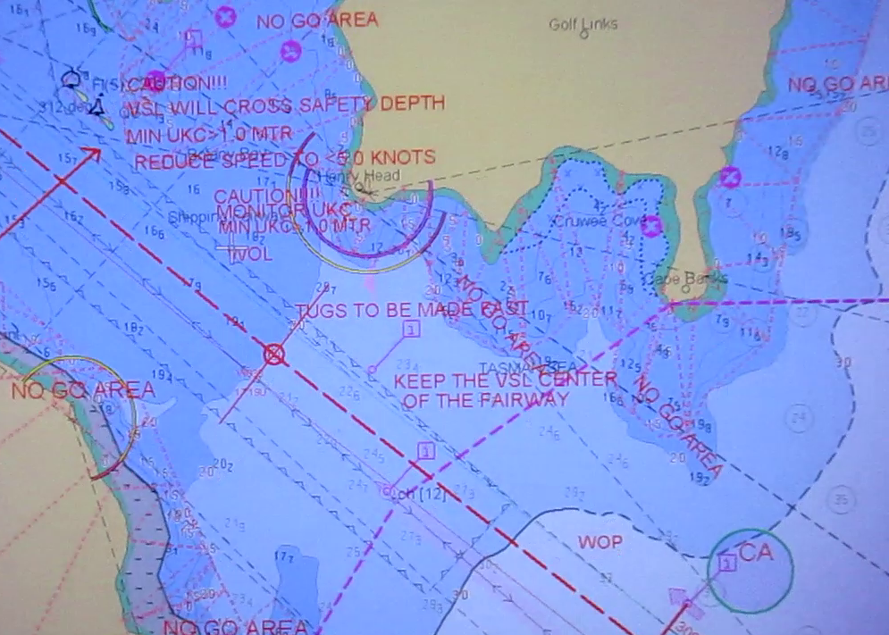
CONFIGURING ECDIS FOR CROSSING SAFETY CONTOUR
a. Calculate safety depths and enter into ECDlS
b. Select viewing groups for soundings, seabed features and contours to be displayed
c. While running route check, if passage is found to be navigating safely through Safety contour, it will be required to draw an artificial safety contour.
d. Construct a manual update line to create an artificial Safety Contour equivalent to the safety depth, using the highlighted safety depth as an indication of the contour
e. Allow a safety margin where depth values displayed are less than the safety depth value.
f. Use existing contours to establish the likely shape of the manual contour
g. Set the manual update Line as an alarmed feature (refer to ECDlS manual and training course notes for guidance)
h. Run the route check facility to confirm that the feature will alarm
i. Ensure the plan is clear when the Safety Contour should be set to the artificial value and reset once the area is clear
j. Save as part of the Voyage Plan in ECDlS and note the feature in the Voyage Plan notes for review and approval by the Master.
k. The areas where vessel’s track is to navigate through Safety contour, should be mentioned in Passage plan and discussed in passage plan meeting.
l. If there is tidal window required to cross such area, same to be noted on ENC.
MARKINGS ON THE ENC
ENC allows navigating officer to insert additional information using ‘Navigator’s Notes’ or ‘Mariner’s Information Overlays (MIO). Such facility allows the placing of text notes, any symbols in the presentation library or simple lines / areas with or without colour fill. The presence of a text note will be identified in the chart area at the defined geographical point by a ‘!’ or ‘i’.
2 thoughts on “USE OF ECDIS FOR PASSAGE PLANNING”