
Stowage on container vessels
The modern container vessel is also divided into holds, but using a similar system for containers would be impossible as a hold may contain anywhere between 50 to 250 containers and the port stay is in hours.
Some system to identify each slot in which a container could be loaded had to be developed to avoid errors in location and stowage.
Three-dimensional system
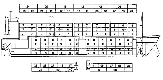
The system used on a container vessel is based on the principles of identifying a point in space. In 3-dimensional co-ordinate geometry a point in space is identified by its co-ordinates in the three axes, i.e. P (x, y, and z) is completely identified. The slot numbering used on a container vessel follows the same principle. The three axes are the longitudinal axis, the athwartship axis and the vertical axis.
Simple Identification of bays
Every container slot in the longitudinal axis is called a bay. Each bay is given a 2-figure number. The numbering of bays could be consecutive numbering starting from 01 onwards. Some ships use this method. The problem with this method is there is no way to distinguish between 20 foot and 40-foot bays and when two 20-ft. containers are loaded in a 40-ft. bay.
Identification of bays taking into account the 20 and 40 foot containers
In order to overcome this problem, another numbering system is used, where the first 40-ft. bay starts with 02 and four are added to the previous bay to identify the subsequent bay. Thus we have bays 02, 06, 10, etc. Where a 20-ft. bay exists they are numbered with odd numbers on either side of the 40-ft. bay number. Thus 2 -20ft containers in say, bay 10, would have the numbers 09 and 11. This system is also in use on some vessels. The problem with this system is that given a bay number it’s not readily apparent which container is being referred to.
Most commonly used system
The most commonly used system, which overcomes all the problems, is where the first 40-ft. bay is numbered 04. Subsequent bays are in multiples of 4, thus 04, 08, 12 etc. If 20-ft. containers are loaded in a 40-ft. bay they are numbered with the odd numbers on either side of the number of the 40-ft. bay. Thus two 20-ft. containers in bay 16 would result with the forward one being numbered bay 15 and after one being numbered bay 17.
It is to be noted that in the absence of a formal convention, all three systems are in use but the last one is the most common.
Rows
Every slot in the athwartship axis is called a row; the numbering of rows is by consecutive numbers, 01, 02, 03, etc. In keeping with tradition, all odd numbers are to starboard and all evens to port. Numbering starts from centre outward; this is because rows in various bays of the ship will vary depending on the position of the bay. Maximum rows are in the mid-length area decreasing to the ends. This row numbering provides uniformity at all bays. Where odd numbers of rows exists, the central row is numbered 00.
Tier
In the vertical axis, each slot is called a tier and is numbered using consecutive even numbers, thus we have 02, 04, 06, etc., tiers on deck are numbered starting from 82 onwards, thus 82, 84, 86, etc. This is again because numbers of tiers in various bays vary as per location and such numbering clearly differentiates between under deck and on deck stowage.
Thus if we say a container in slot 27 05 86, we have the following:
a) 27 being odd number, it is a 20-ft. container. Since the nearest number divisible by 4 is 28, it is in the seventh 40-ft bay in the forward slot.
b) The row is the 3rd from centre to starboard.
c) It is on the third tier on deck.
The main advantage of such slot numbering systems is that they can be used with data processing systems.
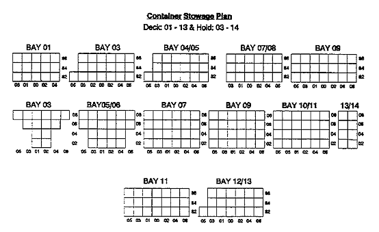
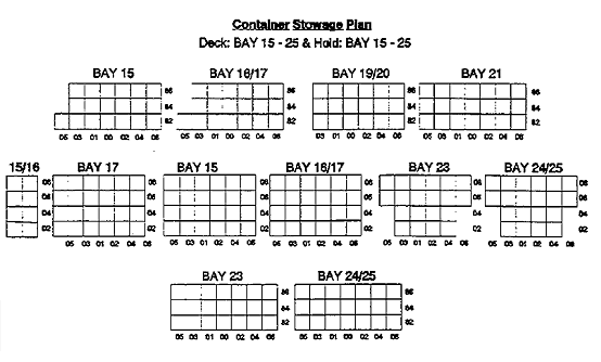
Bay plans
On a general cargo vessel, a cargo stowage plan is a graphical display using side elevation and plan view. Such systems cannot be used for a container vessel. On a container vessel a stowage plan is depicted for each bay separately. The rows and tiers at each bay are shown as squares and each square is filled with the container data. Separate plan is used for deck and under deck for each bay. A main line container vessel having bays up to say 44, (i.e. 11 x 40-ft. bays) may have a bay plan consisting of more than 22 pages.
Stowage planning
The planning of the stowage of containers on a container vessel is generally done ashore, this is because the turn around time of a container vessel is very short and expecting the ships’ officers to plan would unnecessarily delay the vessel. On main line vessels (i.e. those going on definite routes mainly round the world or across the pacific or Atlantic) most companies use a central planner who plans the vessel for the whole voyage. Central planners are sometimes called central co-ordinators. They plan vessels for the ports in their areas. A ship may therefore be handled by more than one planner in one complete voyage.
Such planning becomes necessary, as data of all containers booked at various ports would have to be accounted for in the stowage plan. Every port sends its bookings for the vessel, giving details of container size, approximate weight and cargo characteristics to the central co-ordinator who prepares a pre-stow plan. Such plans are generally based on weight categories. This pre-stow plan is sent to the respective ports and these will then enter the actual container number and weight and load the vessel accordingly. The central co-ordinator will then be updated and he will make the necessary changes to the next port plan.
Even though the planning is done ashore and the ship’s staff is not involved, this is only as an aid to the ship’s staff and legally the Master is still responsible for the correct stowage of the vessel. The Chief Officer therefore has to check this stowage to ensure that the vessel will be safe throughout the voyage and it is his duty to approve the stowage plan. The ship’s officers will therefore have to be conversant with the factors that affect the stowage plan.
Factors affecting stowage plan
The factors to be taken into account when preparing a stowage plan are as follows:
1. Port rotation.
2. Stability, including GM and trim.
3. Stack weight.
4. Strength calculations, SF and BM.
5. Torsional moments.
6. Size and type of containers.
7. Flexibility.
8. Special containers.
Port Rotation
As with all stowage planning, this is the first and the most important factor. All cargo for a discharge port must be available directly for discharge, without the need for any shifting. Any shifting involved will mean additional cost as well as delay.
Stability
The main consideration here is the vessel’s GM. Container vessels tend to have a low GM because of the large amount of deck cargo involved. The loss of GM on passage is also high because of the high speeds and hence high consumption of fuel on these vessels. Consumption in the range of 70 to 120 tons / day are normal for a 2500 teus (twenty equivalent units) vessel having a speed of 24 kts. Due to the deck cargo, a large windage area also exists. The Stability requirements for wind heeling moments also have to be satisfied. Low GM creates problems for manoeuvring because of heel during turning at high speeds and large rate of turns have to be avoided. Container vessels generally carry ballast in D. B. tanks as well as large amount of fuel to increase GM. Ballast carried in wing tanks including upper wing tanks helps to improve the GM and the rolling period. As far as possible, heavy containers are loaded at the bottom. Reduction of free surface, especially in fuel tanks also helps considerably.
A quick check of stowage can be achieved by comparing tier weights at each bay. In general, upper tiers should have less weight than the lower once unless different ports are involved.
Additional constraints
The additional ballast and fuel adds to the dead weight and load line limits have to be taken into account. Generally a container vessel is full by volume rather than weight, except when winter load lines apply. The trim should also be considered and cargo should be distributed evenly for optimum trim.
Stack weight
On a general cargo vessel, the load at any point must not exceed the permissible load density. In case it does, then laying dunnage increases the area over which the load rests. The weight of a container is distributed over the ‘Four Corners’. On a container vessel, the internal structure of the vessel distributes the load over the strength members of the hull. The maximum load that can be borne at the Four Corners of the cell guides is termed as the stack weight. In planning the stowage, this maximum stack weight must not be exceeded.
Strength calculations
Planning must ensure that the shearing forces and bending moments do not exceed the permissible values for the ship. An even distribution of the weight will ensure this. In case even distribution is not possible then it can be compensated for by ballast.
Torsional forces
This is an angular force, which tries to twist a structure. Consider a beam as shown in the diagram.
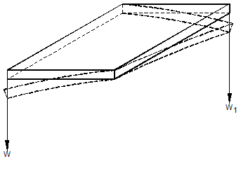
Consider two weights W and W1 hung as shown. The beam will remain horizontal, but torsion moments will exist at the ends. If the torsion becomes excessive, then the point will tend to deform and shear as shown.
Torsional forces exists on all ships, the two causes of torsional forces are (a) sea and swell and (b) uneven distribution of cargo. The effect of these forces depend on
- Length of the vessel
- The freeboard of the vessel and
- The beam of the vessel.
Cargo ships being small in length do not suffer large torsional forces. Bulk carriers and tankers being large both in length and beam do give rise to large Torsional forces. However there is generally very little uneven distribution of cargo in the athwartship direction in such ships and therefore the maximum Torsional forces are due to the sea only and the vessels are built to withstand such forces.
In the case of container vessels, the length, beam as well as the freeboard is large. Container ships have, in addition, uneven distribution of cargo; this results in the ship experiencing large Torsional moments. The only controllable factor is proper distribution of weights on board. The distribution of cargo in each bay must be even when planning stowage. Where it is not possible to have an even distribution in the bay, the Torsional moments at the bay must be reduced to below the allowable Torsional moments using ballast in the tanks at the bay. Correcting the imbalance at another area will not reduce the Torsional moment at that bay.
Remember Torsional stress is a local stress
The moments caused by the cargo can be calculated by stack weight x distance from centreline on each side. The difference between the two gives the torsion at that point. Torsional moments at any point are the summation of the Torsional forces at all such points before the bay in question.
Size and type of containers
In planning the stowage, the size and type of containers need to be known so that the right containers are planned for the right slot. 40-ft containers can only be loaded in 40-ft. bays. 20-ft. containers can be loaded in 40-ft. bays but the ends away from the cell guides cannot be secured and are free to shift. To prevent this either they have to be secured to deck vertically using twistlocks or stackers, or over stowed with a locking 40-ft. container. The latter method is the most commonly used, because loading a row with 20 ft. containers will generally result in excess stack weight, as the load in two 20 ft. containers is more than one 40 ft. container. A 40-ft. container can be loaded on two 20-ft. containers, but two 20-ft. containers cannot be loaded on a 40-ft. container, as the container has no vertical supports in the middle and hence, will collapse. 45-ft. containers can only be loaded in bays meant for such containers or on the third tier of 40-ft. bay. 45 ft. containers have corner fittings at 40 ft. and 45 ft. hence they fit on top of 40 ft. and can be locked. The third tier stowage is to ensure that lashings lead properly and the extension does not obstruct anything. Any other sizes will have to be stowed in dedicated slots.
Containers, which are ventilated, should be stowed on deck or in holds where ventilation is possible. Other specific containers will have to be stowed as per requirements.
Flexibility
A container vessel calls at a large number of ports and loads and discharges at each. Having ensured that the port rotation is accounted for initially, it now becomes necessary to ensure that it is maintained at all subsequent loading ports immaterial of the destination of the container. This is flexibility.
Consider a 4 x 4 matrix of slots and 16 containers to be loaded 4 for each ports A, B, C & D in that order. A simple distribution would be as shown, but this creates problems if 4 containers are to be loaded at Port A for all three remaining ports.
| A | A | A | A |
| B | B | B | B |
| C | C | C | C |
| D | D | D | D |
Alternatively the distribution could be as follows:
| A | B | C | D |
| A | B | C | D |
| A | B | C | D |
| A | B | C | D |
Such a distribution again creates problems if no cargo is available at port A or at any subsequent port. An acceptable distribution would be as follows:
| A | A | B | A |
| A | B | B | B |
| D | C | D | C |
| D | C | D | C |
In short every port should in general have a bottom stow from where the loading sequence can be built up. On main line vessels every port is given a bottom stow. The amount of slots allotted would depend on the cargo expected from that port. A bay is divided into (P) (C) & (S) and for large quantities of cargo the whole bay may be allotted or either (P) & (S) or only (C). For trimming purposes slots are allotted both for’d and aft.
Ship’s Responsibility
In actual practice, the planner for that port presents the Chief Officer with a ‘discharge plan’ and the ‘proposed load plan’. The ‘discharge plan’ is a bay plan indicating all the containers, which will be discharged in that port. Although the port of discharge is clearly indicated in all the Bay Plans, this updated list is the one, which the Chief Officer has to consider, as discharge ports are sometimes subject to change. Moreover, some containers may have their discharge port as an option between 2 or more ports – and this ‘discharge plan’ will indicate which exactly will be discharged in the present port. The ‘proposed load plan’ is a bay plan indicating the weight, port of discharge, and special characteristic of the container, if any (e.g. – IMDG code, oversize etc). As most container ships have computer based loading programs, the Chief Officer will then ‘discharge’ and ‘load’ the containers in his computer program as per the plans given to him. If there is a violation of any of the parameters like the stack weight, SF, BM, maximum allowable trim/list etc., he will get an automatic warning indication. If this happens, he then brings this to the notice of the planner who then changes the proposed stow so as to come within the permissible stability parameters. The Chief Officer has to pay particular attention to the IMDG containers and ensure that they are stowed in accordance with the IMDG code, which specifies the segregation and separation requirements for all IMDG cargo. It must be remembered that all this goes on while container operations are in progress, and any proposed changes have to be quickly brought to the notice of the planner to avoid delays and any extra moves.