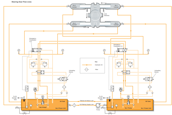
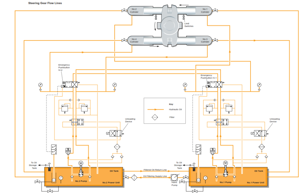
The steering gear consists of two rams and four cylinders that are driven by two electrically driven pumps. The pumps are of the variable displacement axial piston type of swashplate design for closed circuit transmissions and are contained in separate oil tanks.
The steering gear is capable of operating as two totally isolated steering systems with each system having a single pump. Although the hydraulic systems are normally linked, isolation valves are fitted which isolate the systems so that each pump will supply a different pair of cylinders. Each pump unit is capable of putting the rudder through the working angle in the specified time. The steering gear system will normally operate with a single pump working, the rudder turning time from 35° to 30° is 28 seconds with one pumps operating. When maneuvering two pumps are used but when at sea on passage one pump will normally be used.
The steering gear is provided with an automatic isolation system which enables the steering gear to be divided into two independent systems in the event of an oil leak being detected. Both hydraulic systems are interconnected by means of electrically operated isolating valves which, in normal operation, allow both systems together to produce the torque necessary for moving the rudder, even with one pump operating. In the event of failure that causes a loss of hydraulic fluid from one of the systems, the automatic isolation system closes one of the isolating valves so that there are two independent systems, each operated by a pump if both pumps are running but one system being powered and the other isolated if one pump is running.
After a delay of 5 seconds (maximum) a visual and audible alarm is indicated on the bridge and in the machinery space indicating that the steering gear automatic isolation system has operated to separate the two systems.
The automatic isolation system operates to ensure that the hydraulic circuit in which the leakage has occurred is shut down or prevented from operating and only the hydraulic circuit without the fault will operate. Each hydraulic tank has an oil level sensing unit which senses low level and low-low level; the oil level sensing unit is fitted in a chamber in the oil tank. The chamber is fitted with a drain valve which enables the oil level sensing unit chamber to be drained thus activating the low level and low-low level alarms for testing.
The steering gear is remotely controlled by the autopilot control or by hand steering from the wheelhouse. Emergency control is carried out locally by means of a trick wheel which must be engaged with the pump control lever after the bridge control linkage is disengaged. All orders from the bridge to the steering compartment are transmitted electrically. Steering gear feedback transmitters supply the actual position signal for the systems. The rudder angle is limited to 35° port or starboard by means of limit switches and mechanical stops are positioned at 37° port and starboard.
The variable flow pumps are operated by a control lever, which activates the tilting lever of the pump cylinder, causing oil to be discharged to the hydraulic cylinders. When the tiller reaches the set angle, the tilting lever is restored to the neutral position, which causes the pump to cease discharging. No.1 pump motor is supplied with electrical power from the emergency switchboard and No.2 pump motors from the main switchboard. Under normal circumstances at sea, all four hydraulic ram cylinders will be in use, with a single pump units running.
Automatic Isolation System
The steering gear is provided with an isolation system which automatically changes the steering gear operation to isolate a section of the hydraulic system in the event of pipe or other failure. When starting the steering gear, a check must be made to ensure that the automatic isolation system is operating. Indicator lamps in the contactor cabinet and on the bridge indicate that the automatic isolation system is operating.
Each oil tank that is fitted has an oil level detecting unit which will initiate an alarm at low level and low-low level. In the event of a pipe failure or other defect which involves oil loss, the level in the oil tank falls and the low level alarm is activated; a visual and audible alarm is issued. Activation of the low level alarm causes the automatic isolation system to operate, closing the automatic isolation valve associated with the tank which has activated the low level alarm
If the No.1 pump is operating and the low level alarm is activated, the two systems will be isolated but No.1 pump will remain running. If the leak is in No.2 system the oil level in No.1 tank will not drop any further as the leak has now been isolated in the No.2 system; No.1 pump will remain operating but it will only supply its two hydraulic cylinders (No.1 and No.2) thus the available steering gear torque will be reduced to 50%.
However, if the leak is in No.1 system, the oil level in No.1 tank will fall further as oil leaks out of the system. The low-low level alarm will be activated in No.1 tank and the automatic isolation control system de-energizes the automatic isolating valve (closing the valve) and stops No.1 pump; at the same time the control system energizes isolating valve (opening the valve) and starts No.2 pump. The system now runs with No.2 pump supplying its two associated cylinders (No.3 and No.4). No.1 system, in which the leak has occurred is now isolated and the leak may be corrected, the steering continuing with No.2 pump operating on its two associated cylinders with a torque 50% of the full torque.
If No.2 pump is running when the low level alarm is activated the isolation system operates in the same way as that described above except for the pump numbering. If both pumps are running when a low level alarm is activated the systems are isolated and the system which then initiates a low-low level alarm is shut down.
Procedure to Put the Steering Gear into Operation
The system valves are assumed set for normal operation.
a) Check the level and condition of the oil in the tanks and refill with the correct grade as required.
b) Check that the control lever pins are correctly fitted.
c) Ensure the rudder is in the mid position.
d) Start the two electro-hydraulic pump units.
e) Carry out pre-departure tests.
f) Check for any abnormal noises. Check for any leakages and rectify if necessary.
g) Check the operating pressures.
Note: Although the steering gear system may be started, and shut down, from the bridge it is essential that the duty engineer witnesses a machinery start and shut down at least once per month in order to check for any abnormal conditions which may only be present during starting or shutdown.
Operating Procedures
Normal Operation from the Bridge
a) Start and stop the pumps from the control console. Both pumps must be started for manoeuvring.
b) Switch the automatic isolation system to the AUTO position.
c) When full-away at sea in open waters shut down one pump and operate the steering gear with one pump. Change the running pump every 24 hours.
Operation from the Steering Gear Compartment
In an emergency the steering gear can be controlled from the steering compartment using the trick wheel. This unit must be connected to the pump control linkage after the bridge control connection to the linkage has been disconnected. Operation from the steering gear compartment is required in the event of failure of the bridge control system or the telemotor unit.
a) Contact the bridge by telephone and follow the instructions regarding rudder movement.
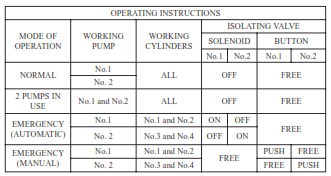
b) For manual operation of the steering gear with the trick wheel both solenoid valves must be OFF (de-energised). The solenoid valve pushbuttons must be set as below depending upon which pump is running. Only one pump may be used when operating on manual local control.
Automatic Isolation System Alarm Condition
When the automatic isolation system alarm is activated:
a) Reduce the ship’s speed immediately to a maximum of 66% of normal full speed.
b) After a maximum period of 45 seconds the automatic isolation system will automatically restore steering capability; see above for a description of the operation of the automatic isolation system.
c) The restored steering torque will only be 50% of the normal torque as two cylinders will not be operating.
d) When the automatic isolation system has restored steering the engineer must take action to physically isolate the defective system and undertake a repair, if possible.
e) Repair the fault immediately if possible and return the automatic isolation system to AUTO when the steering gear is back to normal operation.
Emergency Steering
Emergency steering will be engaged if there is a failure of control from the wheelhouse or if there is a serious leak of hydraulic fluid from the system.
The steering gear consists of a tiller turned by a 4 cylinder hydraulic ram system. Hydraulic power is produced by two electric motor driven variable displacement hydraulic pumps and in accordance with IMO regulations the hydraulic power circuits and rams can operate as two isolated systems.
Two separate conditions have to be considered with respect to emergency steering, The first is loss of control from the wheelhouse and the other is a serious loss of hydraulic fluid from the system.
Loss of control from the wheelhouse
In the event of failure of the control system from the wheelhouse the steering gear must be operated manually from the steering gear room. Rudder angle or course requirements are passed to the steering gear room by means of a telephone and the operator in the steering gear room manually controls the steering gear by one of two methods.
Energency Steering Selector Switch
First a selector switch in the steering gear room may be selected to the emergency position. Two pushbuttons marked port and starboard are then used to send a signal to a hydraulic servo motors which turns the rudder accordingly. There is a heading indicator in the steering gear room so steering may be effected by rudder position commands or heading command.
Secondly a manual wheel called a trick wheel may be engaged by screwing a pin into a yolk, which is connected to a screwed rod and the trick wheel and so to the pump stroke linkage, which is turned to port or starboard again to rudder position commands or heading command.
Loss of hydraulic fluid
The steering gear is fitted with an automatic safety system which is used to isolate the hydraulic power circuits in the event of a hydraulic oil loss from the oil tanks or from a damaged part of the hydraulic system.
In accordance with IMO regulations, the hydraulic pumps used in the steering gear are supplied with power from two independent sources. In the event of power failure from the main switchboard No.1 pump can be supplied from the emergency switchboard.
Operation of the Steering Gear on Loss of Bridge Control
a) On loss of steering gear control from the bridge, establish communication between the bridge and steering gear compartment via the telephone system. A telephone is located in the steering gear compartment for this purpose and is equipped with a head set. There is also a rudder angle indicator and compass repeater in the steering gear compartment.
Using the trick wheel
b) Start one of the hydraulic pump units
c) Remove the connection pin from its stowage point. Place the connection pin in the connection hole between the trick wheel linkage and the pump control lever (this is marked ‘For Emergency’; it may be necessary to rotate the trick wheel slightly to align the holes.
d) Operate the steering gear by rotating the trick wheel in the desired direction until the desired rudder angle is reached. Ensure that the rudder has moved to the desired angle by visually checking the rudder angle indicator adjacent to the trick wheel.
Using the selector switch
e) select the switch to position 2 EMERGENCY.
F) Use the PORT and STARBOARD pushbuttons to steer.
Note: When in trick wheel operation, the hard over rudder angle is 34.5°, port or starboard.
Emergency Steering Solenoid
Oil Purification System
The steering gear is fitted with an oil purification filter system which consists of a hand pump, filter and stop valves. The stop valves must be opened and the hand pump operated clockwise for about 5 minutes. This pumps oil through the filter element. At the end of pumping the stop valves are closed. The cleaning unit must be operated once each week.
The filter unit has a coloured indicator which is green if the element is in a clean condition. When the filter element is dirty the indicator changes to a red colour, pumping must be stopped and the filter element cleaned or replaced. After cleaning or replacement of the filter element the reset pushbutton is depressed and the indicator colour returns to green. The pumping may then recommence.
System Checks
Daily Checks
• Check the oil level in the oil tanks and refill as necessary: the level should not exceed ¾ of the glass at normal working temperature.
• Check the system pipework and valves for leakage.
• Check the grease lubrication system and replenish the grease pump units as required.
• Note the temperature of the oil in the hydraulic system.
• Visually check the components such as indicators and linkage arms.
• Check gauges for any abnormal readings.
• Check for abnormal noise when the rudder is moving.
Monthly Checks
• Check the tightness of all coupling bolts and pipe connections.
• Check the settings of limit switches.
• Carry out a function test on the entire alarm system (see operating manual).
• Check that the rudder indicator is functioning correctly.
Automatic Isolation System Checks
The functioning of the automatic system should be checked once each week when it is convenient and safe to do so. Ideally this should be done as part of the pre-departure checks.
For each power unit drain the oil level sensing unit chamber by opening the drain valve. The low level alarm will be activated causing the pump systems to be isolated and then the low-low level alarm will shut down the pump on that unit.
Restore the system to normal after the test and ensure that the oil level sensing unit chamber drain valves are properly closed.