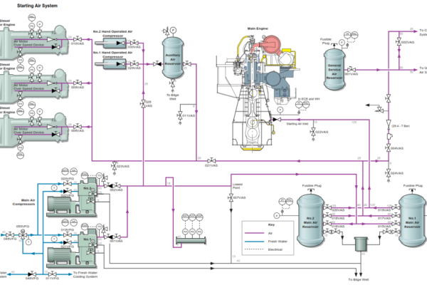
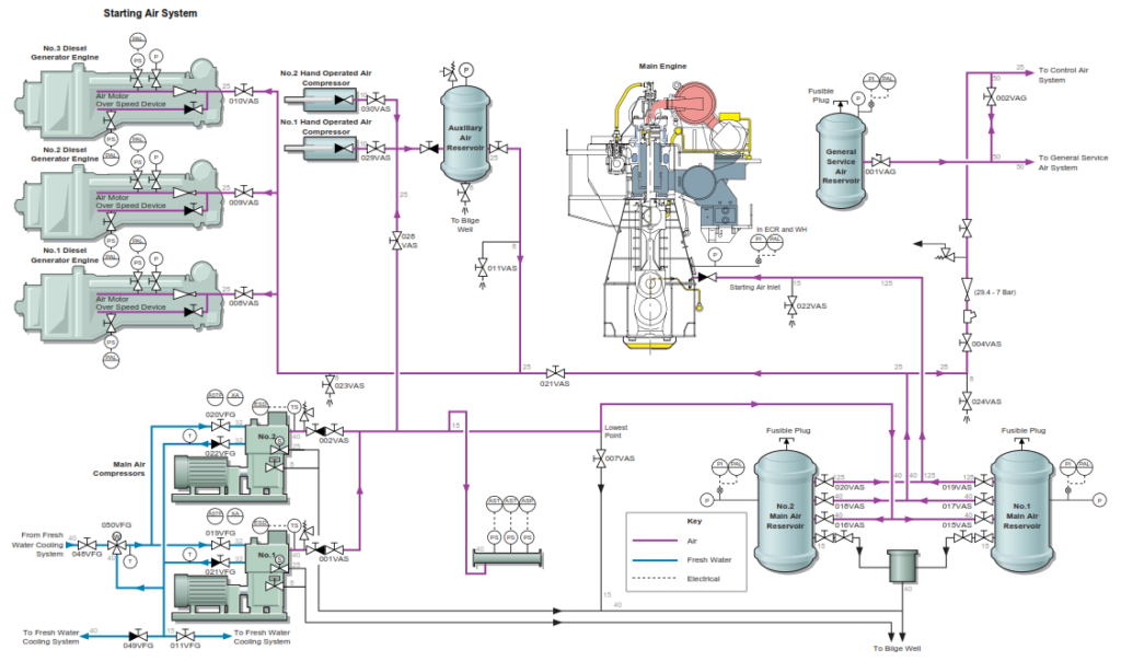
The starting air system is supplied by two main starting air compressors that supply two 5.0m3 starting air receivers. The compressors are of the two stage reciprocating type and are cooled by fresh water from the fresh water cooling system. A three-way temperature controlled valve is used to regulate the flow of water to the compressors to maintain the correct operating temperature.
Each starting air compressor has its own cooling water circulation pump which operates whenever the compressor is running. The starting air compressors operate on a ‘lead’ and ‘lag’ principle and are set to automatically start when the pressure in the starting air receiver falls to a preset value. The lead/lag control is located on the main switchboard No.1 main air compressor starter panel on GSP No.1. The lead compressor cuts in at 2.8MPa and the lag compressor at 2MPa on falling air pressure. Both compressors stop when the pressure reaches 2.94MPa and are controlled by ‘auto start’ and ‘auto stop’ pressure switches fitted on the pipeline between the compressors and the air receivers. The local starter panel is for the main air conpressors amnd the general service air compressor and comprises start pushbuttons and stop/lock off buttons. Selection of automatic operation is carried out at the main switchboard
Both of the compressors have an automatic unloading arrangement on the first and second stage valves which operate when the compressors start and stop. This allows the compressors to start and stop off load so reducing the loading on the electric motor and the wear and tear on the drive train.
The main air receivers are used to supply the starting air for the main engine and for the three diesel generator engines with the air being supplied to the three generator engines using a separate pipeline from that used for supplying the main engine. Illustration above shows the layout of the system and how the pipework is configured. The control air and general service air systems can also be supplied from the starting air system through a reducing station should the control and general service air compressor become inoperative.
Both compressors are equipped with a high air temperature trip which shuts down the machines when the set point is exceeded. A low level LO trip is also provided which will shut down the machine when the oil level in the sump drops below a preset level. A time delay has been provided to compensate for the movement of the vessel in heavy weather.
The auxiliary air receiver is normally supplied from the main starting air compressors but can be directly supplied from one of two hand air compressors in the event of ‘dead ship’ conditions. The compressed air in this receiver is used to start at least one of the three generator engines when the main starting air receivers are isolated. This will allow a generator to be connected to the main switchboard and normal electrical supplies to the engine room resumed. The starting air is supplied to the air motors on each of the engines which then engage with the toothed rim of the engine flywheel. The air is supplied to the starting air motor via a reducing valve fitted on each of the engine starting air lines.
Note: The principal method of starting the vessel from dead ship remains via the emergency generator, which is supplied with 2 battery sets, and in the event of starter motor failure, a spare starter motor.
The generator engine starting air supply valves on the main air receivers and on the air supply lines are normally left open to ensure that any standby generator can be started automatically or locally at any time.
Switches at the compressor starter panels enable the compressors to be manually started and stopped if required. When in remote operation mode, the starting air compressors are normally selected for automatic operation. Before a compressor is started the compressor outlet and the air receiver filling valves must be open. The instrumentation and pressure switch valves must also be open to allow the compressor to operate automatically. It is also necessary to ensure that the automatic drain traps fitted to the bottom of both air receivers are open at all times.
Procedure for Operating the Starting Air System
a) Ensure that all of the pressure gauge and instrumentation valves are open and that the instrumentation is operating correctly.
b) Check the oil level in the compressors and check also for the presence of water in the crankcase.
c) Ensure that the auxiliary fresh water cooling system is operational and that the compressor cooling water inlet and outlet valves are open. Check that the temperature controlled three-way valve is operational .
d) Only one receiver should be in use during normal operations at sea as this will maintain a reserve should a pressure loss occur in the system. One main starting air receiver will, therefore, be maintained at full pressure with the outlet valves closed. The other main starting air compressor will have its filling valve open and the outlet valve to the generator engines open.
Note: Condensed water that accumulates must be drained from the starting air receivers and it is essential that the drain traps are operational on both of the main starting air receivers.
e) Set up the valves as shown in the table below.
The valve settings listed below have assumed that both of the starting air compressors are available for operation and that both of the starting air receivers are open for filling and air discharge:
| Position | Description |
| Open | No.1 starting air compressor discharge valve |
| Open | No.1 starting air compressor outlet valve |
| Operational | No.1 starting air compressor drain valve |
| Open | No.2 starting air compressor discharge valve |
| Open | No.2 starting air compressor outlet valve |
| Operational | No.2 starting air compressor drain valve |
| Closed | Line drain valve |
| Open | Automatic start pressure switch valve |
| Open | Automatic stop pressure switch valve |
| Open | Automatic stop pressure switch valve |
| Open | No.1 main air receiver filling valve |
| Open | No.1 main air receiver drain trap valves |
| Open | No.1 main air receiver pressure gauge valve |
| Open | No.1 main air receiver main engine air supply valve |
| Position | Description |
| Open | No.1 main air receiver generator engine air supply valve |
| Closed | No.1 main air receiver manual drain valve |
| Open | No.2 main air receiver filling valve |
| Open | No.2 main air receiver drain trap valves |
| Open | No.2 main air receiver pressure gauge valve |
| Open | No.2 main air receiver main engine air supply valve |
| Open | No.2 main air receiver generator engine air supply valve |
| Closed | No.2 main air receiver manual drain valve |
| Closed | Main engine starting air line drain valve |
| Open | Generator engine air supply line valve |
| Closed | Generator engine air supply line drain valve |
| Open | No.1 generator engine air inlet valve |
| Open | No.2 generator engine air inlet valve |
| Open | No.3 generator engine air inlet valve |
| Closed | Auxiliary air receiver filling valve from main air compressors |
| Closed | Auxiliary air receiver filling valve from No.1 hand air compressors |
| Closed | Auxiliary air receiver filling valve from No.2 hand air compressors |
| Closed | Auxiliary air receiver filling valve |
| Closed | Auxiliary air receiver outlet valve |
| Closed | Auxiliary air receiver outlet line drain valve |
| Open | Line supply valve to control air/general service air reducing valve |
| Closed | Line drain valve |
| Open | Line valve from reducing valve to control air/ general service air systems |
Automatic Operation
For automatic operation of the starting air compressors:
f) Select the lead/lag compressor at the main switchboard.
g) Ensure that power is available to the main air compressor starter panel. Set the mode switch to AUTO at the main switchboard
g) Press the START pushbutton. The lead compressor will run off-load for approximately 15-20 seconds after which time the drain/unloading solenoid valves will be energized to close and allow the discharge of compressed air to the system.
The compressors will now be controlled by the air system pressure switches according to the setting of the selector switch for the lead and follow-on compressors. At 5 minute intervals the drain solenoid valves are de-energised for 2 seconds to drain water from the compressor air cooler water separator bowls.
When the pressure switch indicates a full pressure in the air receiver, the solenoid valves are de-energised. The drain opens and the compressor unloads and stops. When the pressure in the air receiver falls to the recharging pressure a recharge signal is sent to the compressor. The compressor starts again with the drain valve open so that the compressor actually starts off load. When the compressor is running at normal full speed the drain valve is closed and the compressor loads.
If the air receiver pressure continues to fall despite the lead (duty) compressor operating, the standby compressor will start when the pressure falls to the preset low low pressure. This compressor will start and load in the same manner as the duty compressor and will unload when the cut out pressure for this machine has been reached.
Manual Operation
For manual operation of the starting air compressors:
h) Ensure that power is available to the main air compressor starter panel and press the start pushbutton
The compressor(s) are now started and run in the manual mode. The compressors will continue to be protected by their alarms and shutdowns as in the automatic mode of operation.
The compressors may be operated individually in the manual mode either from the local starter panel or from the main switchboard room.