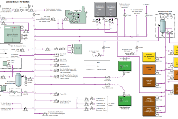
The general service air system is supplied by one electric motor driven air compressor operating at a pressure of 6.9MPa. The compressor discharges to a 3.0m3 air receiver and is controlled by the pressure in the receiver with the machine loading and unloading as required.
The compressor is fitted inside an acoustic casing that is equipped with a local control panel. This provides a digital read out of the system pressure, the air temperature at the compressor outlet and the operating status of the machine. It is menu driven and can be used to obtain operating information or details on alarms and shutdowns.
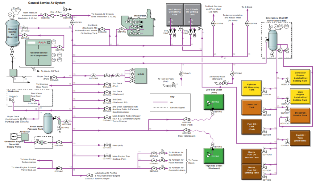
The general service air system is normally supplied by the general service air compressor and the general service air receiver, however in the event of a failure of this compressor, air can be supplied from the main starting air system through a reducing station.
The general service air system is used to supply the following ships services:
• Radar mast air horn
• Foremast air horn
• Generator engine emergency diesel oil pump
• Air conditioning room
• Accommodation services
• Deck services
• Foam room
• Foam alarm air horn
• Pump room alarm horns
• Engine room service air system
• Purifier room
• Incinerator atomising air
• Workshop
• Sea chests
• Main engine exhaust valve sealing air
• The steering gear room
• Main engine turbocharger cleaning
• Fresh water hydrophore tank
• Emergency shut-off valve air vessel
• Fuel valve test rig
Procedure for Preparing the General Service Air System for Operation
The general service air compressor is started by pressing the START pushbutton on the local control panel. The compressor will automatically start and load itself unless the line pressure is above the pressure cut-in set point or the start temperature is below 5°C.
a) Ensure that all the instrumentation valves are open.
b) Check the oil level in the compressor.
c) Set up the valves as shown in the following table. Valves are shown as open but valves for user services will only be open when that service is being used.
| Position | Description |
| Open | Inlet valve to reducing valve from starting air system |
| Operational | Reducing valve |
| Open | Outlet valve from reducing valve from starting air system |
| Open | Line valve to general service air system from reducing valve |
| Open | General service air compressor outlet valve |
| Open | General service air receiver inlet valve |
| Open | General service air receiver outlet valve |
| Open | General service air receiver drain trap valves |
| Open | Upper deck port service air outlet |
| Open | Main engine and No.1 and No.3 generator engine turbocharger service air outlet |
| Open | LO purifier and No.2 generator engine turbocharger service air outlet |
| Open | Deck service air outlet and foremast horn |
| Open | Bridge deck service air outlet |
| Open | Incinerator service air supply valve |
| Open | No.1 waste oil settling tank air supply valve |
| Open | No.2 waste oil settling tank air supply valve |
| Open | MSD air supply valve |
| Open | Port foam air horn valve |
| Open | Starboard foam air horn valve |
| Open | Low sea chest (port) service air supply valve |
| Open | High sea chest (starboard) service air supply valve |
| Open | Fuel valve test rig air supply valve |
| Open | Fresh water hydrophore tank air supply valve |
| Open | Generator engine blackout FO pump air supply valve |
| Open | Main engine turbocharger cleaning and exhaust valve sealing air supply valve |
| Open | Air horn for general alarm air supply valve |
| Open | Air horn for foam release air supply valve |
| Open | Air horn for gas detector air supply valve |
d) Start the general service air compressor, ensuring that the loading and unloading system operates correctly. The cut in and cut out pressures are set during the commissioning of the system and should not be changed.
e) Check that the system drain traps are operational.
The general service air system is now operating with air supplied by the general service air compressor via the general service air receiver, however, the valve set up described shows the valves from the starting air pressure reducing valve being open. This will ensure the automatic supply of back-up air from that system in the event of general service compressor failure or excessive demand from the service air system.
Switching off the compressor is achieved by pressing the STOP pushbutton on the compressor’s local control panel. The green light will extinguish and the compressor will go through its timed shutdown sequence.