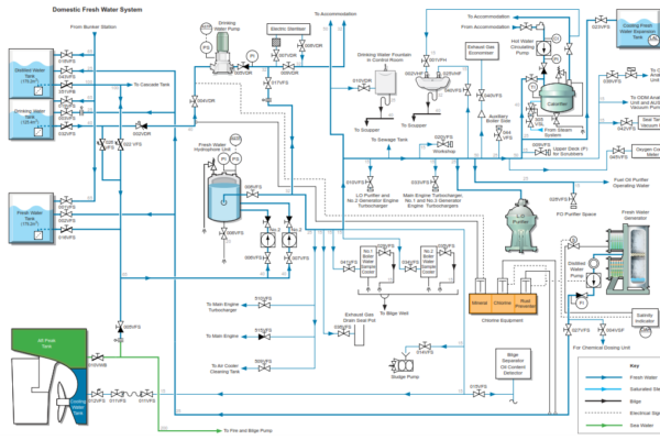
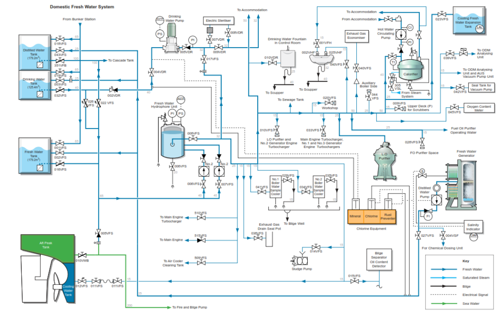
Fresh water for domestic use is stored in the fresh water tank located in the steering gear room. Drinking water is supplied by a separate system and the drinking water is stored in the drinking water tank also located in the steering gear room.
Fresh water and drinking water is pumped to the tanks from the evaporator.
Distilled Water Transfer and Distribution.
The water is treated with chlorine and rust inhibitor before being discharged to the fresh water and drinking water storage tanks. Domestic fresh water does not require further treatment before being distributed around the ship via the fresh water hydrophore system.
Drinking water requires further sterilising and the addition of essential minerals before it is fit for human consumption. Drinking water is distributed throughout the ship by the drinking water pump and the drinking water is treated by the addition of mineralising chemical before the drinking water pump suction.
The dosing rate is set to maintain the correct level of minerals in the drinking water. The water must be tested at weekly intervals in order to ensure that the treatment is correct. The drinking water pump starts and stops automatically according to the pressure in the drinking water system. At the drinking water pump outlet there is an ultraviolet sterilizer which can be bypassed if necessary
Fresh water is taken from the fresh water storage tank and pumped to a hydrophore tank from where it is distributed around the ship as fresh domestic water and as technical water for use in the machinery spaces. Both the domestic and technical water systems are supplied by the same single hydrophore unit. There are two pumps which pressurise the hydrophore tank, one pump is selected as the duty pump and the other pump is available as the standby pump should the duty pump fail. The system supplies water at a rate of 8.0m3/h.
Cold water is also supplied to the calorifier from the fresh water hydrophore unit where it is heated and circulated around the domestic hot water system. The calorifier is a 1.8m2 heating surface area thermostatically controlled horizontal storage and heating vessel which utilises steam or electricity to provide the heat. The electric heater is reserved for use when the steam plant is shut down or during periods of refit. The water is heated to 70°C and is then circulated around the ship by the hot water circulating pump. By continuously circulating the water in this way, wastage is kept to a minimum with water not having to be run off to obtain hot water through to an outlet tap or connection.
The domestic fresh water system is used to supply the following:
• Sanitary system
• Calorifier and accommodation hot water services
• LO and FO purifier operating water systems
• Exhaust gas boiler washing
• HT/LT cooling water expansion tanks
• Seal tank for vacuum pump unit
• Sludge pump
• Boiler water sample coolers
• Oily bilge water separator oil content detector
• ODME analysing unit cleaning water
• Generator engine turbocharger cleaning
• Main engine turbocharger cleaning
• Main engine air cooler cleaning
• Oxygen content meter
In an emergency the fresh water system can supply water to the drinking water system via a connection after the drinking water pump and before the sterilizer. Care must be taken when using this facility as the fresh water has not had minerals added and these are essential for drinking water as distilled water will leach valuable minerals from the human body. Steps must be taken to ensure that mineralizing chemicals are added to the fresh water if it is to be used for drinking water.
Operation of the Domestic Fresh Water System
| Position | Description |
| Open | Fresh water tank outlet valve |
| Closed | Line valve to after peak tank |
| Closed | Crossover valve from distilled water tank |
| Open | No.1 hydrophore pump suction valve |
| Open | No.1 hydrophore pump discharge valve |
| Open | No.2 hydrophore pump suction valve |
| Open | No.2 hydrophore pump discharge valve |
| Closed | Hydrophore tank outlet valve to fresh water system |
| Closed | Line valve to drinking water system |
| Open | Engine room washbasin supply valve |
| Open | Hot water system make-up valve |
| Open | Hot water pump inlet valve |
| Open | Hot water pump outlet valve |
| Open | Calorifier outlet valve |
| Open | Hot water supply valve to engine room washbasin |
Technical Water Distribution System
Fresh water is used for a number of purposes throughout the ship and all systems are supplied by the hydrophore pumps via the hydrophore tank. Set the technical water system valves as in the following table. Valves to services are shown as in the Closed position, the valve being set to the Open position when that service is operational and requires a supply of fresh water.
| Position | Description |
| Closed | Exhaust gas drain sealing pot inlet valve |
| Closed | No.1 boiler water sample cooler inlet valve |
| Closed | No.2 boiler water sample cooler inlet valve |
| Closed | Sludge pump priming water valve |
| Closed | Bilge separator oil content detector |
| Closed | Outlet valve at engine room floor aft (for connection to stern tube cooling water connection) |
| Closed | Outlet valve at No.2 generator engine turbocharger |
| Closed | Outlet valve at main engine and No.1 and No.3 generator engine turbochargers |
| Closed | Outlet valve in workshop |
| Closed | Outlet valve to No.1 LO purifier |
| Closed | Outlet valve to No.2 LO purifier |
| Closed | Exhaust gas economiser washing water valve |
| Closed | Outlet valve at auxiliary boiler side |
| Closed | Outlet valve in FO purifier space |
| Closed | Outlet valve to No.1 FO purifier |
| Closed | Outlet valve to No.2 FO purifier |
| Closed | Oxygen content meter supply valve |
| Closed | Supply valve to seal tank for vacuum pump unit |
| Closed | ODM analysing unit supply valve |
| Closed | Outlet valve at upper deck for scrubber |
| Closed | Cooling fresh water expansion tank supply valve |
| Closed | Fresh water supply valve to sewage treatment unit |
| Closed | Main engine turbocharger air cooler cleaning system |
| Closed | Main engine air cooler cleaning tank make-up water valve |
| Closed | Main engine turbocharger water washing water valve |
The valves supplying the spaces or pieces of equipment listed above can be opened individually as necessary.
There is a direct water supply line to the ODME analysing unit and AUS vacuum pump unit; these devices have their own isolating valves.
Procedure for Setting-up the Hydrophore System and the Calorifier
a) Start one FW hydrophore pump.
b) Fill the hydrophore tank to about 75%.
c) Stop the hydrophore pump.
d) Connect the compressed air supply line to the tank and slightly open the air inlet valve until the operating pressure is reached.
e) Close the compressed air supply valve.
f) Repeat steps b) to e) until the tank is at the correct operating pressure, with the water level at about 75%.
g) Switch one hydrophore pump to AUTOMATIC operation and open the hydrophore tank outlet valve.
The hydrophore system is now ready for operation
h) Slowly open the hydrophore tank outlet valves to the domestic water system and the technical water system until the system is pressurised.
i) Start the hot water circulating pump.
j) Vent air from the calorifier.
k) Start the electric heater for the calorifier.
l) Open the calorifier drain valve and the steam supply valve , when steam is available from the 0.88MPa system.
m) Ensure the calorifier’s steam inlet temperature control valve is operational and able to take control of the heater.
n) Shut down the electric heater.
Procedure for Operating the Drinking Water System
a) Ensure that the mineraliser unit on the water treatment plant is operational
b) Set the valves as in the following table.
| Position | Description |
| Open | Drinking water tank outlet valve |
| Closed | Line crossover valve from distilled water tank |
| Open | Inlet valve to the drinking water pump unit |
| Closed | Outlet valve from the drinking water pump pressure tank unit |
| Closed | Line valve from fresh water hydrophore system |
| Open | Ultraviolet steriliser inlet valve |
| Open | Ultraviolet steriliser outlet valve |
| Closed | Ultraviolet steriliser bypass valve |
c) Set up the drinking water pressure tank in the same way that the hydrophore tank was set up in the procedure for operating the fresh water hydrophore system.
d) When the drinking water pressure tank is at the correct operating pressure open the outlet valve and supply drinking water to the drinking water system. Set the drinking water pump to automatic and check that it stops and starts automatically to maintain the desired system pressure.
e) Check the ultraviolet steriliser for leaks and when it is found that the system is secure start the ultraviolet steriliser.
f) Check the operation of the ultraviolet steriliser lamp. Open drinking water outlet valves at the extreme ends of the drinking water system to allow water flow through the system. When all system water has passed through the ultraviolet steriliser the drinking water system is ready for operation.
g) During operation of the drinking water system a check must be made to ensure that the steriliser lamp is illuminated and that the mineraliser dosing unit is operating correctly. Drinking water must be tested weekly in order to ensure that it is fit for human consumption.