Introduction
To ensure a fast and effective ability to respond to a fire situation the ship is provided with means to shut off tanks containing flammable liquids that would normally be open; to shut down the pumps and other equipment that could cause or maintain a fire and to shut off air supply to the fire.
Oil Tank Quick-Closing Valves
CAUTION
Some tanks such as lubricating oil tanks do not have quick-closing valves fitted. This is because they are normally closed and only opened for short periods of time when required. It is therefore important to ensure that these valves are always closed when not in use.
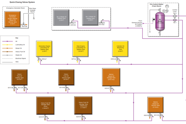
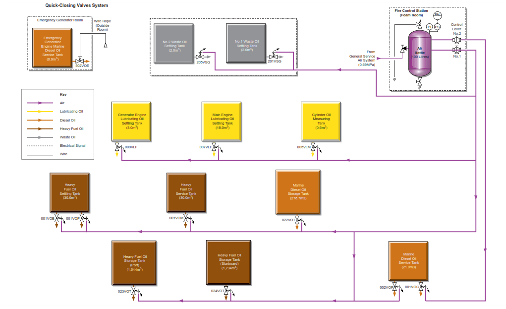
All of the outlet valves from the fuel oil and lubricating oil tanks from which oil could flow to feed a fire are equipped with pneumatically operated quick-closing valves. These valves are operated from the fire control station located on the upper deck in the starboard forward area of the accomodation block.
The valves are supplied with compressed air at 0.69MPa from a 100 litre storage bottle located in a cabinet in the fire control station. The bottle is fitted with an alarm to warn of low pressure and is fed directly from the engine room general service air main. A non-return valve is fitted on the inlet line which is normally left open to ensure that a full charge of air is always available. The oil tanks are grouped into two systems as shown in above diagram, with one three-way cock operating each system.
In normal operation the supply line to each group of tank valves is vented to atmosphere, but when the cock is turned, compressed air is directed to the pistons, which collapse the bridge of each valve in that group, thus causing the valve to close.
The valves are reset by venting the air supply and operating the valve handwheel in a closed direction to reset the bridge mechanism and then opening the valve in the normal way.
The exception to the above operating system is the MDO tank for the emergency generator. This valve is operated locally from just outside the space by a cable pull wire.
The main sea suction valves are operated remotely by hydraulic systems from handwheels located on the 3rd deck level in the engine room.
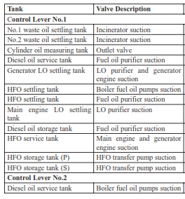
The valves listed in the following table all relate to the diagram as shown above.
Emergency Stops
There are five emergency stop pushbuttons and each control a number of fans or pumps and are operated from a number of locations as follows:
Emergency Stop Switch ES1: Accommodation Space Fans and Hydraulic Pumps
This group may be operated from the wheelhouse and the fire control room
Accommodation air conditioning compressor
Accommodation air conditioning supply fan
No.1 and 2 Hydraulic pumps for deck machinery
No.1 and 2 Hydraulic pumps for valve control system
Galley supply fan
Galley exhaust fan
No.1 and 2 sanitary exhaust fan
Steering gear room and emergency fire pump space exhaust fan
Emergency Stop Switch ES2a: Engine Room Fans Fuel Oil Pumps and Lubricating Oil Pumps
This group may be operated from the fire control room
No.1 Main engine auxiliary blower
No.1 Auxiliary boiler forced draught fan
No.1 Camshaft lubricating oil boost pump
No.1 Fuel oil supply pump
No.1 Purifier lubricating oil feed pump
Lubricating oil transfer pump
Sludge pump
No.1 Engine room ventilation fan
No.1 Generating engine lubricating oil priming pump
No.3 Generating engine lubricating oil priming pump
No.1 Auxiliary boiler control panel
Engine control room unit cooler
Emergency fuel oil supply pump
No.1 Inert gas fan
No.1 Main lubricating oil pump
No.1 Fuel oil circulating pump
No.1 Auxiliary boiler fuel oil burner pump
Engine room ventilation fan
No.2 Generating engine lubricating oil priming pump
Incinerator control panel
Emergency Stop Switch ES2b: Engine Room Fans Fuel Oil Pumps and Lubricating Oil Pumps
This group may be operated from the fire control room
No.2 Main engine auxiliary blower
No.2 Auxiliary boiler forced draught fan
No.2 Camshaft lubricating oil boost pump
No.2 Fuel oil supply pump
No.2 Purifier lubricating oil feed pump
Diesel oil transfer pump
No.2 Purifier fuel oil feed pump
No.3 Engine room ventilation fan
No.2 Generating engine fuel oil supply pump
No.2 Inert gas fan
No.2 Auxiliary boiler control panel
No.2 Main lubricating oil pump
No.2 Fuel oil circulating pump
Bilge pump
Purifier space exhaust fan
No.2 Heavy fuel oil transfer pump
Emergency Stop Switch ES3: Pump Room Fan
This group may be operated from the fire control room
Pump room exhaust fan
Emergency Stop Switch ES4: Galley Equipment and Galley Fans
This group may be operated from the outside the galley
Electric cooking range
Electric dishwasher
Galley supply fan
Electric baking oven
Minor power distribution board
Garbage disposal unit
Galley exhaust fan
Dough mixer
Electric deep fat fryer