Inert gas system
The salient features of the inert gas regulations are listed below
- The inert gas system is designed and operated to render and maintain a non-flammable atmosphere in the cargo tank at all times until required to be gas free.
- The system is capable of delivering Inert Gas (IG) at 125% of the maximum rate of discharge.
- The system is capable of delivering IG with oxygen content not more than 5% by volume.
- The scrubber is capable of cooling the flue gases and removing solids and sulphur. It is installed aft of all cargo spaces, pumprooms and cofferdams.
- At least two blowers are provided to supply the IG to the tanks and they are located aft of all cargo spaces, pumprooms and cofferdams.
- IG generator may be fitted with only one blower provided sufficient spares for the blower and prime mover are available and the crew is capable of rectifying any defects.
- Two fuel oil pumps are provided for the inert gas generator but the administration may permit only one pump provided sufficient spares are carried and the crew is capable of rectifying any defects in the pump.
- The IG system is so designed that the maximum pressure, which is exerted on the cargo tank, does not exceed the test pressure of the tank.
- The system design including location of scrubber, blowers and piping shall be such that leakage of IG into enclosed spaces is prevented.
- To permit safe maintenance an additional water seal or other effective means of preventing flue gas leakage are fitted between the flue gas isolating valve and the scrubber.
- At least two non-return devices are fitted in the IG system to prevent the return of hydrocarbon into the machinery space. One of these is a water seal.
- The water seal shall be supplied with water by two separate pumps each one being capable of supplying the required water.”
Note: Nitrogen generators are now used on Chemical tankers due to the nature of Nitrogen (No soot or water carry over).
The system consists of the following components
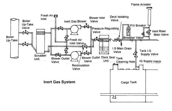
Boiler uptake valves
Two pipes used to direct the Flue gases emanating from the boiler uptake are connected to the scrubber by means of valves called the boiler up take valves. These valves must be kept open when the inert gas system is in use and needs to be shut if the system is used for gas freeing purposes. An indication of the status of these valves is provided on the mimic control panel. Automatic means to clean the valve seats by air and water are also provided to keep the valve seats free of dirt and soot deposits.
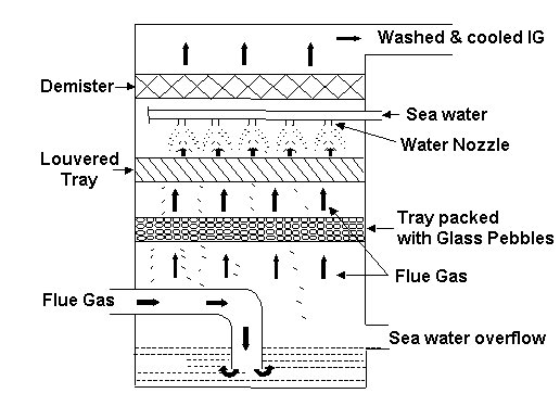
Scrubber
The scrubber is a rubber-lined unit in which the flue gases from the boiler enter at the bottom. The scrubber has a continuous supply of water, which flows out through the overflow line. The flue gas bubbles through the water and passes through trays packed with stones or plastic chipping, perforated impingement plates or such other arrangement to ensure maximum contact between the flue gas and water.
The flue gases are cooled by the contact with water and solid impurities in the flue gases are removed. The scrubber is designed to remove at least 90% of the sulphur dioxide in the flue gas. The discharge of water from the scrubber should be led to the shipside in such a way that at the maximum loaded draft there should be no adverse back pressure which will affect the working of the scrubber.
The top part of the scrubber has a demister, which removes any water that may be carried over in the flue gases.
IG blowers
IG system has at least two blowers whose combined capacity is 125% of the maximum discharge rate that the cargo pumps can achieve. Some ships have one large blower and one small blower, the combined capacity being 125% of the maximum discharge rate. The advantage is that the smaller blower can be used for topping up and the larger one during discharge operations.
Most ships have both blowers of identical characteristics and this ensures that even if one blower is not operational the ship can continue discharge, though at lesser rate.
The blowers are washed with fresh water after use. The fan casing has a fresh water connection provided and after the power supply to the fan is stopped, the fresh water valve is opened and the fan impeller and casing is washed to remove soot and other deposits. The water should not be started when the fan is in operation as the impeller may then get damaged.
Oxygen Analyser
On the discharge side of the blower, a sample line leads a sample of IG into an oxygen analyser. The oxygen analyser determines the oxygen content in the IG. If the O2 content is 8% or above, the blower discharge valve closes and the IG is vented to the atmosphere through a vent line. The oxygen analyser must be calibrated at regular intervals and a record maintained.
Fresh air intake
There is an intake provided on the deck through which the blower can supply fresh air into the tanks. While using the IG system the fresh air intake is kept blanked. There are interlocking devices provided to ensure that the IG plant is not operated with the fresh air intakes are open. If the percentage of oxygen is found high, ensure that the fresh air intake is not leaking.
Pressure regulating valve
The pressure-regulating valve is on the IG panel and it maintains the IG pressure at the set value. The operator sets the IG pressure desired and the pressure-regulating valve recirculates the excess IG back to the scrubber.
Deck Seal
The deck seal is a positive means of ensuring that the contents of the cargo tanks never reach the machinery spaces. There are three types of deck seals, viz-
- Wet type
- Semi-dry type
- Dry type.
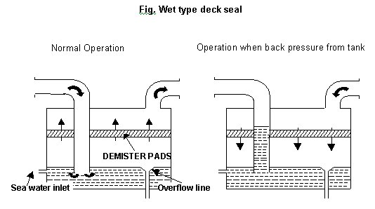
Wet type deck seal
In this type of deck seal, the IG enters the deck seal at the bottom and bubbles through the water. The water carried by the IG is removed in the demister. Refer to figure. If there is a back pressure from the cargo tanks then the water is forced into the pipe bringing the IG from the blowers thus preventing the gases from the cargo spaces from entering the machinery spaces.
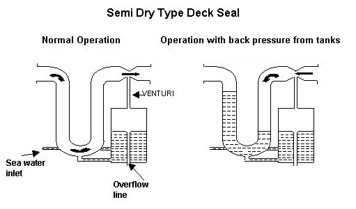
Semi-dry type
In this type of deck seal, when the IG is not operational the U pipe is full of water. As soon as the IG starts flowing the plug of water in the U pipe is pushed aside and the flow of IG causes a ‘Venturi’ effect. This draws the water from the U pipe into a separate holding chamber. If there is back pressure from the cargo spaces the venturi effect disappears and the water flows back into the pipe and since there is a continuous supply of water to the holding tank, the passage of gases is effectively prevented.
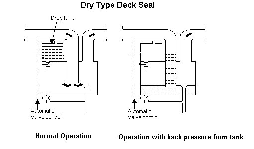
Dry type
In this type of deck seal, the water is held in a ‘Drop tank ‘and when the IG plant is in operation the water is drained and if the system is stopped or if there is back pressure from the tanks then the seal is filled with water. The filling and discharge of the drop tank and the seal are done automatically by valves, which monitor the level of water in the ‘Drop tank’, deck seal, and the state of the blowers. There is no water carry over in this type of deck seal.
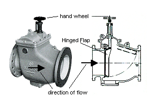
Non return valve
This is normal mechanical non-return valve. It is provided with a flap, which can open only in the direction of the cargo tanks thus allowing IG to flow to the tanks. If there is pressure from the tanks, the flap of the non-return valve closes preventing passage of gases to the machinery spaces. Means are available to lock the flap shut. This must be kept in the unlocked position when the inert gas system is in use.
Deck isolating valve
This is normally a butterfly valve, which is opened when the IG is to be delivered to the tanks. It may be remotely controlled from the cargo control room or manually operated. This valve should be shut immediately after stopping the IG plant.
Sampling valve
This is a small valve provided after the deck isolating valve and is used to tap off a sample of the IG for checking the quality of IG being delivered to the deck. This valve is also used to check if there is any water carried over in the IG.
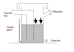
PV breaker
This is liquid filled equipment as shown in the figure. Its function is to release the build up of excess pressure / vacuum in the cargo spaces.
This equipment does not need any maintenance except that the correct grade of liquid should be filled to the exact level.
The liquid used is fresh water + glycol mixture or suitable grade of oil. The liquid used should not freeze at the lowest temperature experienced by the vessel. If there is buildup of excessive pressure, the breaker will ‘Blow’ i.e. the liquid in the breaker will be blown out to the main deck and the gases in the tank can vent to the atmosphere. In case of a vacuum in the tank, the liquid will be drawn into the IG line, and this will allow the outside atmosphere to enter the tank. Normally the PV breaker is a last means which will become operational to release the pressure / vacuum in the tank. The PV valve comes into operation to release the pressure / vacuum before the PV breaker.
PV Valve
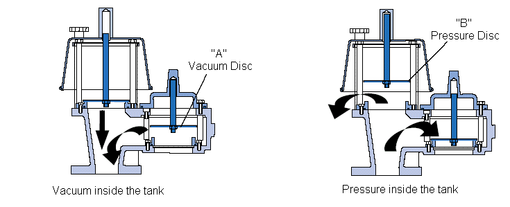
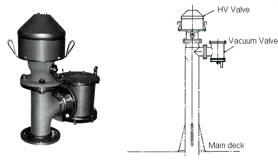
This is also called as the ‘Breather Valve’ and is meant to release the excess pressure / vacuum built in the tank due to rolling / pitching / temperature change. The PV valve operates normally at half the pressure at which the PV breaker operates. Refer to figure below.
Most PV valves have two weighted discs, which could be termed as vacuum disc ‘A’ and pressure disc ‘B’. As the pressure in the tank rises it exerts pressure on weight ‘A’ and ‘B’. Disc ‘A’ cannot move in the direction in which the pressure is being exerted but disc ‘B’ moves upwards on reaching the set pressure allowing the gases inside the tank to vent to the atmosphere.
If there is a vacuum in the tank, disc ‘A’ is lifted as soon as the set value of the vacuum is reached and the outside atmosphere can enter the tank to relieve the pressure. Spark arrestors are provided to prevent the entry of a spark into the tank.
High velocity PV Valve
Normal PV valves release the pressure at about deck level. The gases then tend to settle on the deck if there is no apparent wind. This can, besides being uncomfortable for the crew on deck, be a fire and explosion hazard. Hence, most PV valves are fitted with cones on the pressure side, which direct the flow of gasses high into the air. These are called high velocity PV valves.
Mast riser
This is an arrangement to vent the tank atmosphere while loading cargo. Since the gases vented during loading are in large volume, the mast riser is used. The mast riser is a vertical pipe, which opens to the atmosphere. It has spark arrestor at the outlet and the control valve is at the base of the mast riser. The mast riser valve is throttled during loading so as to always maintain a positive pressure in the tanks.
IG branch valve
This is normally a butterfly valve at the inlet of the IG line into the cargo tank.
Alarm systems on the Inert gas system
The water flow to the scrubber is monitored either by a flow meter or by pressure gauges; an alarm is initiated when the water flow drops below the designed flow requirements by a predetermined amount, and the inert gas blowers will be stopped automatically in the event of a further reduction in the flow.
The water level in the scrubber is monitored by a high-water-level alarm; this alarm is given when pre-determined limits are reached and the scrubber pump shut down when the level rises above set limits. The inert gas plant will shut down in this case.
The inert gas temperature at the discharge side of the gas blowers are monitored, an alarm is given when the temperature reaches 65° C, with automatic shut down of the inert gas blowers if the temperature reaches 75° C.
For the deck water seal, an alarm is given when the water level falls by a pre-determined amount, but before the seal is rendered ineffective.
The pressure of the inert gas in the inert gas main is monitored; an alarm is given when the pressure reaches the set limit.
When the pressure in the inert gas main forward of the non-return devices falls below 50 millimetres water gauge, means are provided to sound an alarm or to shut down the main cargo pumps automatically.
The alarm is activated if the oxygen content goes higher than 8 %. The alarms must be tested prior every Inert gas operation and at regular intervals.
Additionally, the plant will shut down if the blowers fail, if the control power pails, and if any manually operated emergency stop is activated.