ELECTRONIC CHARTS
There are two types of Electronic Charts available:
a) Raster Navigational Charts (RNC).
b) Electronic Navigational Charts (ENC).
RASTER NAVIGATIONAL CHARTS (RNC)
A RNC is a raster chart that conforms to International Hydrographic Organization (IHO) specifications and is produced by digitally scanning a paper chart image. The displayed data is merely a digital copy of the original paper chart, the image has no intelligence and other than visually, cannot be interrogated. When operating an equipment in Raster Chart Display System mode in the absence of electronic navigational charts, an appropriate portfolio of up-to-date paper charts should be available onboard (IMO MSC 232).
LIMITATIONS OF RNCs
- RNC will not trigger automatic alarms. (e.g. anti-grounding).
- With RNC, it is not possible to display a ship’s safety contour or safety depth ,
unless these features are manually entered during route planning. - RNCs are treated as individual charts (not seamless like ENCs). However, it is possible for ECDIS to automatically load adjoining chart based on the meta data provided.
- Horizontal datum and chart projections may differ between RNCs.
- A display of RNC features cannot be simplified by the removal of features to suit a particular navigational circumstance at hand.
- RNC is intended to be used at the scale of the equivalent paper chart. Excessive zooming in or zooming out can seriously degrade the displayed image.
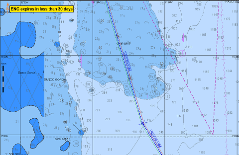
ELECTRONIC NAVIGATION CHARTS (ENC)
ENCs are official vector charts that have been issued by or on behalf of a national hydrographic authority and conform to strict International Hydrographic Organisation (IHO) specifications.
ENCs are the only vector charts that can be used for primary navigation in place of paper charts.
Each point on the chart is digitally mapped, allowing the information to be used in a more sophisticated way, such as clicking on a feature (for example, a lighthouse) to get all the details of that feature displayed.
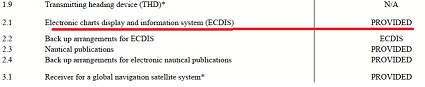
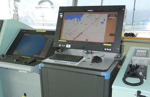
ELECTRONIC CHART DISPLAY & INFORMATION SYSTEM (ECDIS)
ECDIS is defined in the IMO ECDIS Performance Standards (IMO Resolution A.817(19)) as follows:
“Electronic Chart Display and Information System (ECDIS) means a navigation information system which, with adequate back up arrangements, can be accepted as complying with the up-to-date chart required by regulation V/19 & V/27 of the 1974 SOLAS Convention by displaying selected information from a system electronic navigational chart (SENC) with positional information from navigation sensors to assist the mariner in route planning and route monitoring, and by displaying additional navigation related information if required.
DOCUMENTATION FOR APPROVAL OF ECDIS
a. Hardware approval:
A type approval certificate provided by manufacturer for make / model fitted on ship.
A permanent label is attached to the equipment (‘Wheel Mark’ or other equivalent sign).
b. Safety Equipment Certificate Form E:
SEQ Certificate Form E, endorsed ( ECDIS- ‘ Provided”, Back-up arrangement of ECDIS – whether “ECDIS or Paper charts”)
c. Software / Firmware approval:
Latest Software/ Firmware version of ECDIS to be used (IHO and manufacturer provides list of latest software versions for various make / model of ECDIS).
Presentation Library to be checked for version 4.0.
Whether the ECDIS is updated to the latest “Edition of the Standards” is represented by only the first 2 digits of the Edition number. The 3rd digit of the Edition number (in brackets) indicates only a clarification version of the Standard and the clarifications have no impact on safety of navigation or ECDIS performance. Hence, the Presentation Library versions showing different digits in brackets after 4.0 do not pose any concern and no action is warranted for this, e.g., Presentation Library versions 4.0(.1) and 4.0(.2) both are acceptable and safe for use.
d. IHO approved chart supplier for providing official ENCs.
TRAINING / FAMILIARIZATION REQUIREMENTS FOR USE OF ECDIS
a. Generic Training
Master and all Navigating Officers should have undergone an ECDIS training course, complying with IMO Model Course 1.27 at the company’s training institute or at one of ECDIS training institutes, approved by a flag administration on IMO White list, in order to use ECDIS as a primary means of navigation.
b. Type specific equipment training
Master and all Navigating Officers shall undergo necessary formal training in that ship’s type specific equipment i.e. the training should relate to the make and model of the equipment fitted on-board. The equipment specific training should be of minimum 8 hours duration.

Following options are available for achieving familiarization both onboard and ashore. These include and can be a combination of the following, but not limited to:
- Shore based manufacturer’s training followed by installation-specific Familiarisation onboard;
- Independent training on specific systems followed by installation specific Familiarisation;
- Computer Based Training (CBT), followed by installation-specific Familiarisation onboard;
- Internet / Intranet Based Training (eLearning) followed by installation specific Familiarisation onboard;
- Onboard training by appropriately trained crew or training personnel*;
- Manufacturer provided training mode on the ECDIS, followed by installation-specific Familiarisation onboard;
- Company bridge procedures and manuals.
- Trickle down training is not considered acceptable.
c. On-board training
The ECDIS on-board training (relevant to the make and model) is to be completed by the Master and all navigating officers
VESSELS EQUIPPED WITH SINGLE IMO APPROVED ECDIS
While using ECDIS as primary means of Navigation and paper charts as back-up, following must be complied with –
- Vessel shall be fitted with One IMO approved ECDIS.
- Both ECDIS and Paper charts are to be updated and maintained at all times.Weekly corrections, navtex warning, nav area warning, T&P corrections, etc. are to be applied to both ECDIS and Paper charts.
- Passage planning to be replicated on both paper charts and the ECDIS. Drawing of the course line, various markings and information such as contingency anchorage, abort point, VHF channel etc. should be done on both ECDIS and Paper charts.
- Vessel should carry all paper charts for the voyage, as would have been the case if there was no ECDIS, these should be kept ready for immediate use.
- Relevant paper chart of the then navigating area should be kept ready on the chart table with at least one position marked. Master on his discretion can include instructions in his Standing orders to have more frequent position plotting requirement on paper charts e.g. one position on each course line, depending upon the area of navigation.The idea is to ensure that vessel can immediately switch to paper charts without any undue delay in case of ECDIS failure.
- There are certain areas , which are not covered by Electronic Navigation Charts (ENC) , however, covered by Raster Navigation Charts (RNC). For navigating in such areas, Vessel may use RNC in conjunction with updated paper charts,after obtaining office approval.
VESSELS EQUIPPED WITH DUAL IMO APPROVED ECDIS (REQUIREMENTS FOR PAPERLESS NAVIGATION)
After completion of transition process, while navigating with dual ECDIS in paperless mode, following must be complied with –
- The vessel should have two independent IMO approved ECDIS.
- Each vessel fitted with dual ECDIS is to be equipped with small scale charts and any additional flag state requirements must also be complied with.
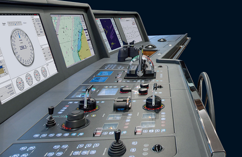
ECDIS INTERFACE
As per IMO performance standards, following minimum interfaces shall be provided to an ECDIS:
a. Ship’s position fixing system.
b. Gyro compass.
c. Speed and distance measuring device.
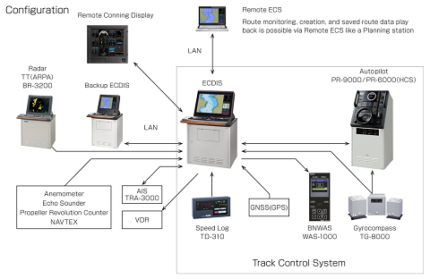
However, most modern ECDIS equipment is provided with following additional interfaces:
a. AIS (automatic identification system).
b. RADAR (radar image overlay RIO).
c. VDR (voyage data recorder).
d. Echo Sounder.
e. NAVTEX.
f. Meteorological instruments such as anemometers (measuring wind speed).
Navigating officers should be aware of which electronic systems are providing sensory inputs to their onboard ECDIS.
Sensory input from alternate sources ( e.g. GPS-1/ 2, Gyro-1/ 2) must be checked on regular interval to ensure their functionality.
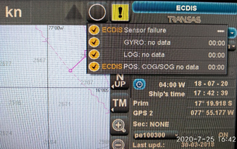
A failure of sensory input will result in loss of some useful ECDIS information. Brief examples of sensory input failure are as mentioned below:
- Gyro Failure: Course over ground (COG) information (from GPS) will be displayed by the ECDIS.
- GPS Failure: The ECDIS will run in DR mode with position being displayed basis heading and speed log input.
- Speed Log Failure: ‘Speed Over Ground’ (SOG) instead of Speed Through Water (STW) will be displayed by the ECDIS.
- AIS Failure: This will result in loss of AIS target overlay. In case of sensory input failure, the Master shall carry out ‘Risk Assessment’ considering following points:
- Identification of sensory input failure and has the failed sensory input affected the navigation of the ship?
- Does it require increase in watch level?
- Implementation of back-up arrangement such as traditional position fixing method etc.
- Amendment to vessel’s intended passage.
CHART PROCUREMENT
Following is the procedure for ENC procurement :
- The navigating officer shall consult the software carrying digital chart catalogue such as admiralty digital catalouge, e-Navigator etc. to find the required ENCs for the forthcoming voyage
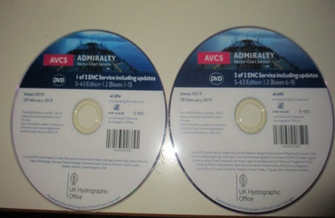
- All ENCs in the world are present in base DVD. Hence, it is important to keep latest base DVD safely on board. However, individual ENC can be made visible only with valid permit.
- Permit / license needs to be purchased for required ENC and then loaded on the ECDIS
- After loading the permit in ECDIS, latest base DVD must be run for ENC data to be visible to user.
Vessel shall use only IHO approved supplier for supply of ENCs. For areas covered by ENC, only ENC shall be used for the navigation. In areas, where ENC is not available, RNC may be used in conjunction with updated folio of paper chart.
Deciding on required ENCs of appropriate scale:
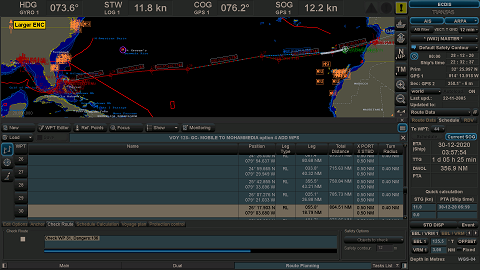
- ENCs can be selected by ticking the Column as marked (see below voyager screenshot for reference). Select only the largest scales first. Start with berthing and then keep going up till Coastal, so that, you do not miss out to order the large scale ENCs. All the largest scale ENC’s on which the track passes should be ordered.
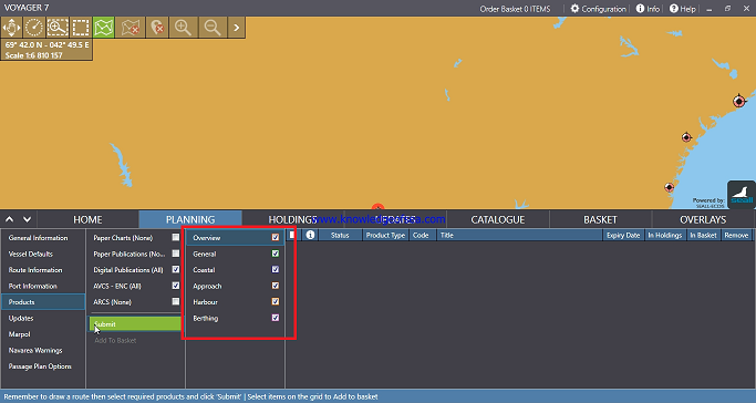
- ENCs have usage bands and the first number of the ENC represents it’s usage band. See below for your reference:
1 – Overview; 2 – General; 3 – Coastal; 4 – Approach, 5 – Harbour; 6 – Berthing. - Following steps should be followed to ensure that all ENCs for the passage are available and up to date:
- Once the route has been prepared by the second mate on the ECDIS, it must be exported to the VOYAGER (or similar ENC ordering software) to verify that all the largest scale ENC’s have been ordered. This is not applicable if the route is prepared directly in VOYAGER.
- Check the ENC status report (Route filtered) on your ECDIS to ensure that all ENCs are updated.
- Carry out a visual scan of the entire route on the best scale to verify that all navigation marks along the passage are visible.
- The chart ordering software uses a default limit of 25 Nautical Miles on either side of the track to order ENC’s, e.g., when passing through the English channel, the software will order all the berthing charts along the coast which will be of no use. Hence, large scale ENC’s (e.g., berthing charts) not on the track and not meant for the purpose of vessels transit may be omitted. When a vessel is coasting, she should use ENC’s of usage bands 3 & 4 and avoid
ordering ENCs of usage bands 5 & 6, unless the track passes over it. Vessels should choose a default limit of 15 Nautical Miles when ordering ENC’s, which allows a deviation of up to one hour if needed. - If all types of ENCs are selected, following issues may be encountered:
- All the ENCs, including the Overview and General ENCs, will show together, which will clutter the view, making it difficult to identify the largest scale ENC.
- The ENC supplier may not send some small scale ENCs, assuming that they are not required for the voyage and while doing so, sometimes may miss out to send the large scale ENC also by mistake.
- If Overview and/ or General ENCs are required to be ordered, vessel should order these separately and not along with the large scale ENCs for the voyage.
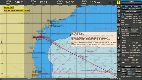
- Many mariners believe that ECDIS will indicate “Larger ENC Available”, if monitoring is being done on a smaller scale ENC. However, it should be borne in mind that this indication comes, only if the larger scale ENC is available in the ECDIS system on board. If the larger scale ENC is not ordered, then the ECDIS may not make any such indication.
CHART CORRECTION
Updating ENC Data:
ENCs are updated by weekly ‘Notices to Mariners’ issued by Hydrographic Offices / Regional ENC co-ordination centers ( RENC) and corrections are received on the vessel either by email or data file (AVCS DVD). The actual updating is either applied to the ECDIS chart database automatically or by the user. The ECDIS generates error message when the update is unsuccessful or when a ENC is in use and has not been corrected up to date.
All masters and navigating officers must be fully aware of how to update and maintain the on board ECDIS. It must not be left for the designated navigating officer to have sole knowledge on the updating procedure and process. Updating principles should be covered under ECDIS generic training but, more importantly, also under the type specific training as different ECDIS models vary in their updating process.
Upon receipt of the ECDIS updates, the Navigating Officer must ensure that the corrections are applied to all ECDIS units fitted on board and verified by the Master. On ships fitted with two ECDIS, both ECDIS should not be kept synchronized with each-other ( Master and Slave) and should be kept independently. The received correction should be applied on back-up ECDIS first. After an interval of 8 hours and conformance that the corrections are correctly showing on back-up ECDIS, the correction is to be applied on the main ECDIS This sequence is to ensure that both
ECDIS does not fail at the same time due to any bug in the correction file
Updates to ENCs are sequential, and the sequence is unique to each ENC. During the updating process ECDIS always checks that all updates in the sequence have been applied. If an update is missing then the ECDIS will indicate this; it is not possible to load later updates until the missing update is applied. The chart system operation’s manual will provide instructions on how to carry out this task.
The ECDIS maintains a list of updates applied and the date of application. This list can be used to check the update status of the ENCs loaded. Port State Control officers may use the ECDIS listing to ensure that ENCs are being kept up to date in accordance with SOLAS chapter V Regulation 27.
AVCS DVDs are sent to vessels from a company approved recognized electronic chart suppliers. However, if it gets delayed due to vessel’s schedule, vessels should directly request weekly correction from UKHO through e-mail. Vessels are provided with approved electronic means, e.g. e-Navigator, Safnav etc. which can be used to assist in management of ENCs on board.
If due to some reason, the updates cannot be received from UKHO by email, vessel must request chart agent immediately to send updated through e-mail.
After updating ENC, modification to the passage plan may be necessary to accommodate new chart features such as reporting schemes, traffic separation schemes, isolated dangers etc. A route check shall be carried out to ensure that any new dangers, which may have been added don’t present a risk to the safety of navigation.
Notices to Mariners (NTM): Much of the information in NTM is only for use on paper charts and is not applicable to ENCs or RNCs. However, vessels navigating solely on ECDIS are still required to carry latest NTM (paper copy or digital) to obtain information such as ‘Radio Navigational Warnings’, ‘Amendments to Admiralty Sailing Directions / Admiralty List of Lights and Fog Signals / Admiralty List of Radio Signals’.
All paper charts on board whether being used as back-up means for single ECDIS ships for dual ECDIS ships must be kept updated to the latest Notices to Mariners onboard.
Temporary & Preliminary Notices (T&P):
Caution must be exercised when navigating solely with ECDIS as some ENC or RNC data may not take account of temporary or preliminary notices.
Temporary and preliminary notices are not handled consistently by all ENC producers at present. Some producers, like the United Kingdom Hydrographic Office (UKHO), incorporate the T&P notices into the ENCs and their updates, whilst others ignore T& Ps completely. The Navigating Officer must check the ECDIS charts to verify whether T& P corrections have been included in the weekly updates.
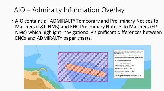
The UKHO use ‘Admiralty Information Overlay (AIO) to incorporate T&P notices within its ENCs. This tool allows the notices to be displayed as an overlay to the ENC in the Admiralty Vector Chart Service (AVCS), thus assisting the navigator in readily identifying the location and content of a notice during passage planning and the voyage itself.
Some of the ENC producers facilitate inclusion of T&P corrections within ENC.
List of ENC producers those allows such inclusion and those who do not, is available in the information folder of the Base DVD.
If it is included, AIO will no longer display the T&P information on ENCs .
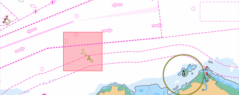
If it is not included, the T&P information will continue to display as red polygons on the ENC and must be plotted manually using the manual Updates.
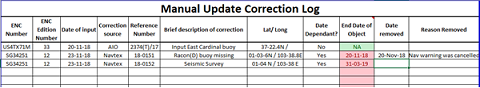
When using charts produced by other sources, notices may be absent. These must be inserted manually as ‘Mariners Objects’ using ‘Marine Information Overlay (MIO) tool. Where ECDIS is unable to display a list of manual update applied, the navigating officer should maintain a record of all the manual updates presently applied on ECDIS . The Navigating Officer must monitor T&P notices closely so that once they are withdrawn they are also removed from the ECDIS charts on board and this list should be kept updated.
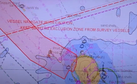
Navarea, Navtex and locally broadcasted Warnings:
Navigational warnings transmitted by satellite and Navtex receiver are by nature more short term and urgent than T&P notices. Such notices shall be immediately plotted on ENCs using ‘Marine Information Overlay’ (MIO) facility, where provided. NAVTEX warnings may be displayed automatically if the NAVTEX is integrated into the ECDIS system.
(A) SOURCES & MANAGEMENT IN ECDIS:
- NAV AREA WARNING:
a. Weekly notices to mariners (Section 3) – Weekly NTM published by UKHO contains Nav warning for Nav area-1.
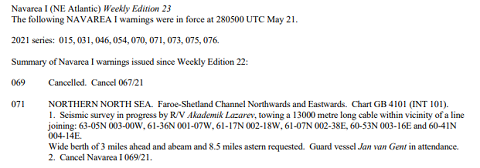
b. SAT-C EGC : As per vessel’s route , OOW should select Nav areas in SAT-C and receive printout of all the warnings currently in force. List of warnings currently in force is received through SAT-C on weekly basis. Alternatively, OOW may request Nav area coordinator and receive all the in force warning through e-mail for nav area relevant to the passage.
These warnings have to be plotted on ECDIS using manual update.
- NAVTEX warning:
NAVTEX warnings are local nav warnings received through Navtex transceiver. Once vessel is within coverage of selected station, Navtex receiver will start printing all the warnings for that particular area covered by that NAVTEX station. Hence, these corrections will be received and applied on ECDIS during the voyage.
If NAVTEX is not integrated with ECDIS, these warnings will have to be plotted on ECDIS using manual update similar to Nav area warnings.
However, if NAVTEX is integrated with ECDIS, these warnings will automatically appear on ECDIS display.
Depending upon source of warning, some warnings will be automatically plotted on ECDIS display with specific detail mentioned in it. O.O.W. will need to match the coordinates of automatic plot on display with the specific details of warning provided. If there is any error in position or the format of position is found incorrect, the warning
plotted on display will be wrong. In such case, this will have to be corrected using manual update.
Some warnings will not be automatically plotted, but, only give an indication such as “N” or “ Navtex Warning no.” at warning location on display. OOW will need to click the warning to see the detail and plot it as a manual update. Hence, all navtex warnings, whether automatically plotted on ENC or not, must be checked by OOW.
(B) DISTANCE CRITERIA:
Company guidelines for minimum distance from route within which nav area/ Navtex warnings must be plotted on ECDIS having seamless charts ( without boundary) :
- All nav –warnings affecting the area of 15 miles on either side of the vessel’s track must be plotted on the ENC and recorded in the passage plan.
- All Nav-Warnings affecting the area from 15-60 miles on either side of the vessel’s track need not be plotted but must be recorded in a section of the Passage plan. However, warnings such as firing practice zone or dangers of similar nature are recommended to be plotted.
(C) LOG KEEPING FOR NAV WARNINGS / NAVTEX WARNINGS:
- Similar to management on paper charts, OOW should check all the warning printouts from SAT-C, NAVTEX, etc. If the warning is relevant to the passage and plotted / noted, the ENC no. should be mentioned on the printout and kept for record with OOW’s signature till conclusion of passage.
- Every time, vessel receives a new voyage order, OOW should check all the warnings currently in force for the passage, plot all the relevant ones as per company’s distance criteria, and delete the remaining if any on that ENC.
Chart Correction Log (NP 133C):
Vessels are required to maintain the ADMIRALTY ENC Maintenance Record (NP 133C). This log is designed by UKHO to streamline the management of paper records of ENC and ECDIS maintenance and make information on official digital
charts more accessible for bridge team.
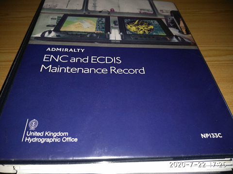
It is similar to the Paper Chart Maintenance Record (NP 133A), which is also produced by UKHO.
The ADMIRALTY ENC Maintenance Record aids inspections, assists SOLAS chapter V carriage compliance and streamlines information management. It is laid out in nine logical sections, with clear templates for bridge team to utilize, in order to make administrative processes faster and more efficient.
Also, by consolidating records into one well-organized folder, it enables inspectors and auditors to quickly see that ENCs and ECDIS are well managed.
The nine sections are:
- Digital Chart Service Certificate
- Schedule A
- ENC Status
- Temporary and Preliminary Notices to Mariners and ADMIRALTY Information Overlay status
- Important Service Notices (e.g. the README file)
- Section VIII of ADMIRALTY NMs
- Cancelled and Withdrawn ENCs
- Maintenance of ECDIS
- ECDIS Installation
The folder sections encourage the bridge O.O.W. to store additional material on general ECDIS maintenance. If all sections are completed and kept up-to-date, the folder can be used as part of the handover process.
LIMITATIONS OF ELECTRONIC CHARTS
- Usage of RNC in ECDIS
As of now, ENC charts do not cover all sea areas. ECDIS charts provided on board are a combination of ENC and RNC. The Navigating Officers should bear in mind limitations of RNC’s.
- Information Layer Filtering
ECDIS may not display some isolated shoal depths when operating in ‘base’ or ‘standard display’ mode. As a result, route planning and monitoring alarms may not always be activated when approaching such dangers. Caution should be exercised whenever information layers are removed or information level is reduced from an ENC and must be reviewed by the Master. All members of the Bridge Team must be advised whenever such changes are carried out. Master’s standing instructions should include instructions regarding minimum layered information to be displayed.
Certain passage plan legs may require addition or removal of some layered information which should be highlighted in the passage plan.
As a minimum the following layered information shall always be used over and above the IMO Standard Display:
- Soundings
- Depth contour labels
- Seabed pipeline labels
- Light descriptions
- Special areas
- Additional information available
- Clearance, bearings, radio channels
- Names for position reports
- Berth and anchorages
- Underwater obstructions
- Chart Corrections / Date of Survey
The Hydrographic offices of various countries process official charts and take on the responsibility of maintaining their accuracy. However, corrections made by these offices might only be available at certain fixed intervals and reliability/ margin of error of a position-fix must be borne in mind.
- Positions
Positions are primarily derived from the GPS / DGPS. Therefore any GPS / DGPS alarms must be immediately investigated in order to avoid error in position and the possibility of the vessel running into danger.
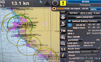
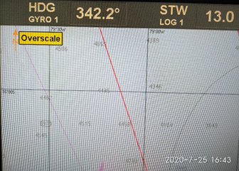
- Scale in Use (Over-scale / Underscale)
There is a risk of running too close to danger with a zoomed-in chart scale. The Navigating Officer should alternatively switch to a smaller chart scale to appraise the situation. All bridge team members shall be aware of the vertical lines on the ENCs indicating over-scale along with visual warning. Using the SCAMIN feature, system automatically filters information from ECDIS display. When the display is zoomed out (underscale) then certain features are suppressed and the operator runs the risk of not seeing all relevant and possible safety critical information. Autoload and autoscale
features are used to minimize the SCAMIN affect. The operator should be careful of the overscale / underscale effects and select the compilation scale (1:1) for display. The primary ECDIS terminal should, where possible, always be set to the compilation scale (1:1).
- Radar Overlay
Positions of other vessels and targets displayed on the ECDIS might be obscured because of improperly tuned radars or improperly set anti-clutter on either the radar or ECDIS. The possibility of offset error is eliminated during the installation phase and later can be recalibrated using the administrative rights in ECDIS.
A Consistent Common Reference Point (CCRP) is a location on own ship, to which all horizontal measurements, such as target range, bearing, relative course/speed, closest point of approach, or time to closest point of approach are referenced.
CCRP setting includes –
a) Own ship’s CCRP location
b) Radar antenna installation location
c) GPS installation location
OOW should ensure that CCRP is correctly set on ECDIS for correct radar overlay display.
- AIS Input
AIS displays target course and speed over ground as well as heading. However, such target information shall not be used for collision avoidance as the AIS data is based on sensory inputs which may be erratic / faulty.
- RADAR Input
An ECDIS equipped with a radar overlay shall only be used as a situational awareness tool during anti-collision manoeuvres and not for primary anti-collision purposes. The ship’s ARPA radars will be used for this purpose.
- Depth Units
Depth unit information is displayed in ECDIS console indicating the depth units in use (meters, feet or fathoms). In case of any changes, the OOW must inform the same to the relieving OOW at the time of handing over the watch.
- Zones of Confidence (ZOC)
CATZOC on the ENC in simple terms refers to the Quality and Accuracy of survey data (Position, Depth, Seafloor coverage) and the applicable accuracy range in chart datum that sometimes can greatly affect vessel’s safety of navigation. Zone of Confidence (ZOC) has 6 Categories named A1, A2, B, C, D and U as shown below:
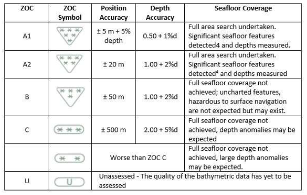
Bridge O.O.W. should be aware of the ECDIS function to activate the CATZOC symbol on ENC. The knowledge of CATZOC is important especially when vessel is passing an area of shallow / restricted waters. These values can affect the vessel’s safety of navigation.
While planning the passage, navigating officer must check and consider the CATZOC for the entire route of the passage, i.e., depending upon the CATZOC value and symbol, the accuracy of the range of position and depth of that area should be born in mind.
The primary importance of CATZOC is seafloor coverage and then the position / depth accuracy.
The depth accuracy is relevant only in areas where full seafloor coverage has been achieved, i.e. areas with CatZOC – A1 & A2.
For other areas with CATZOC – B, C, D or U, full seafloor coverage has not been achieved. Hence, the O.O.W. should leave a safety margin for the possibility of an uncharted ‘surprise’ , which may be much larger than the allowance provided in above table.
Vessel’s passage planning should be done in such a way to avoid passing through an area with CatZOC– B, C, D or U , if UKC is less than 50% of ship’s static draft. However, if vessel has to pass through such area (with UKC less than 50% of Ship’s static draft ), the bridge team should comply with risk mitigating measures such as use of recommended routes / shipping lanes / Traffic Separation Scheme (TSS) or confirmation of depth from agents / publications, etc. This will minimize the chance of encountering an uncharted danger.
CHECKS PRIOR USING ECDIS FOR APPRAISAL AND PASSAGE PLANNING
Following checks should be carried out by the Navigating Officer while carrying out passage planning on ECDIS:
a. Not all sea areas are covered by ENC charts. The electronic chart coverage for the voyage must be adequate and all relevant charts must be fully corrected. For areas covered by ENC, it is mandatory that they be used instead of RNC. If RNCs are to be used, a set of updated paper charts for those areas shall be made available onboard and office shall be informed prior commencement of the passage.
b. Check local requirements of coastal states that may require carriage of additional publications or local charts.
c. Check that electronic charts have been updated to the most recent version and chart permit licenses have been bought.
d. The vessel’s controlling operational parameters (maximum draft, air draft, turning data, minimum under keel clearance required, ‘look ahead’ distance etc.) should be entered.
e. The GPS position system should be set to WGS 84 datum.
f. The alarm functions of the ECDIS should be fully operational; they will alert the operator of any danger exposed in good time during the voyage.
g. Carry out ‘Route Check’ to ensure that vessel will not encounter navigational hazards on the planned route. A visual check of all ENCs being used for the voyage at the best scale must be carried out.
h. When planning new way points and courses, always use the largest scale possible so all features of the chart can be readily identified.
Following measures shall be kept in mind while ordering and using the large scale charts:
i) ENCs have usage bands and the first number of the ENC represents its usage band. See below for your reference:
1 – Overview; 2 – General; 3 – Coastal; 4 – Approach, 5 – Harbour; 6 – Berthing.
ENCs near the coast and approaches will start with a higher number – 3 and above and same must be used when approaching port.
ii) Many mariners believe that ECDIS will indicate “Larger ENC Available”, if monitoring is being done on a smaller scale ENC. However, it should be borne in mind that this indication comes, only if the larger scale ENC is available in the ECDIS system on board. If the larger scale ENC is not ordered, then the ECDIS may not make any such indication.
iii) For ordering the ENCs, once the route has been prepared by the second mate on the ECDIS, it must be exported to the e-Navigator (or similar ENC ordering software) to verify that all the largest scale ENCs have been ordered. This is not applicable, if the route is prepared directly in e-Navigator.
iv) ENCs can be selected by ticking the relevant columns. Select only the largest scales first. Start with berthing and then keep going up till Coastal, so that, you do not miss out to order the large scale ENCs.
v) If all types of ENCs are selected, following issues may be encountered:
- All the ENCs, including the Overview and General ENCs, will show together, which will clutter the view, making it difficult to identify the largest scale ENC.
- The ENC supplier (e.g., C&C Marine, etc.), may not send some small scale ENCs, assuming that they are not required for the voyage and while doing so, sometimes may inadvertently miss out to send the large scale ENC.
vi) If Overview and / or General ENCs are required to be ordered, vessel should order these separately and not along with the large scale ENCs for the voyage.
i. Ensure that the plan takes into account sufficient cross-track error (XTE) to accommodate any deviations for collision avoidance or currents.
j. Ensure adequate values are input for safety contour and depth alarms as per BMM.
k. Check that tidal information is up to date and correct.
l. CATZOC should be considered for depth while checking the available UKC in the passage.
m. Date dependent features which may arise on ENC at a future date must be considered.
USE OF ECDIS FOR ROUTE PLANNING
ECDIS provides many benefits for route planning; a few of which are:
- A quick and easy to select saved routes and prepare new ones.
- Routes can be easily modified with the use of the planning graphic tool.
- Measurements and calculations are much easier.
However, planning a safe route requires experience, time and adequate familiarity with the general principles of ECDIS and navigators should be aware of the following:
a. Check Route Function: The navigating officer should make use of the check route function after passage planning to ensure that vessel will not encounter navigational hazards on the planned route. These hazards would be mainly pertaining to grounding dangers, crossing TSS line / boundary and user defined alarms.
Visual checks at compilation scale prior approving the plan must be carried out. This will assist in overcoming the issues of missed out information due to inappropriate scaling/ display/ SCAMIN of ENC.
b. On coastal passages / shallow waters , ENCs will be populated with many area related cautions. These may result in numerous warnings being generated during the planning stage leading to missing out of critical item alert. It is important that all warnings / alarms are carefully checked.
c. Information on an ENC along the route requires to be accessed in full. The procedure for the complete access to information will depend on the make/ model of the ECDIS and is given in the manufacturer’s manual.
d. Navigators should be aware that a geometrically incorrect alarm will be displayed if the distance between two waypoints is very short or if the turn is very sharp. In such a case, the radius and/ or speed should be adjusted to clear the alarm.
e. Proper appraisal of collecting information from the relevant publications needs to be carried out prior plotting route on the ENC.
f. The finally approved route should then be appropriately saved and also copied to the back-up system.
g. Speed Plan: The planned speed for the leg, which will always be at or below the safe speed, after considering the proximity of navigational hazards along the route, the depth of water and the manoeuvring characteristics of the vessel.
h. Turn Information: This can usually be entered by rate of turn or radius. The system will normally calculate one from the other one, and display both parameters using the planned speed for the leg.
i. CATZOC information to be considered during route planning
j. Markings on the Chart:
The electronic chart should be marked with:
a. Prominent navigation and radar marks
b. Parallel index lines (not from floating objects unless they have been first checked
for position)
c. No go areas
d. Landfall targets and lights
e. Clearing lines and bearings, safe distance off
f. Transits, heading marks and leading lines
g. Significant tides or current
h. Safe Speed and necessary speed alterations
i. Call Master Point/ Changes in Machinery Status and notices for main engine /
Anchor clearance
j. Minimum under keel clearance
k. Crossing and high density traffic areas
l. Contingency plans / Abort positions
m. VTS and reporting points
n. Any other user defined notifications as considered necessary
EXECUTION AND MONITORING
a. Check that the display has been set-up properly prior to sailing, otherwise important information may not be displayed. There are generally three default settings of the layers of an ENC i.e. Base, Standard and Other. The ENCs should normally be in full access mode. In case the text information clutters the other chart information, the text layer may be disabled.
b. Day / Night Settings: The display should be set up to meet the appropriate conditions on the bridge. There are three main viewing modes available: daytime, dusk and nighttime.
CAUTION – When using night / dusk settings, background colours get altered and shoals / other dangers may not be readily apparent. Until good orientation is achieved, it is advisable to switch to Day settings occasionally.
c. Always use ENC on the best scale possible to avoid crucial information being auto filtered and subsequently not being displayed.
d. When executing a route, progress against the original plan must be constantly monitored.
f. Marking and highlighting of electronic charts should be carried out in a similar ways to paper charts. Such marking should identify radar conspicuous targets, no-go areas, parallel index lines, transit marks, clearing bearings, etc.
g. Data input from the gyro compass, speed log, echo sounder and other electronic equipment to the ECDIS should be periodically monitored to ensure accuracy using ‘Sensor Monitor’ window.
h. The look-ahead facility should warn of any hazards ahead off screen but do not rely on it; always use the zoom and scrolling facility to look ahead. Look-ahead range time range for route monitoring is an operator specified parameter. It is important that this time or distance is carefully set to meet the particular circumstances. If set too long it will create numerous alerts that may distract the navigator.
i. Changing of ECDIS cells – Leaving the ECDIS main screen monitoring, when navigating the ship, should only be after ensuring that it does not affect the safety of navigation. This is also a distraction resulting in focus/ attention of the officer on watch being taken away from navigating the ship.
j. Navigating officers must not become over-reliant on ECDIS. Frequent checks should be made of the ECDIS position fixing system (normally GPS) by the use of other means to cross-check and determine vessel’s position.
Such checks should include:
- Parallel indexing and use of clearing bearings.
- Visual cross bearings.
- Use of radar to check the accuracy of the charted position.
- Comparison of signal to noise ratio of the GPS system in use ( HDOP value)
Traditional forms of position fixing should never be overlooked or replaced when using ECDIS; these can include but are not limited to:
– Visual bearings
– Radar ranges and bearings using variable range markers (VRMs) and electronic bearing lines (EBL)– transit bearings and clearing ranges
– Running fixes
– Fixing by a line of soundings
– Horizontal sextant angles (HSAs)
– Positions by celestial means (sextant)
k. If ARPA overlay is used, targets not acquired by the ARPA will not appear on the ECDIS. Similarly targets not fitted with AIS will not appear on ECDIS.
Therefore, ECDIS should not be used as primary means of collision avoidance.
MANDATORY ECDIS ALARMS AND ALARM SETTING GUIDANCE
Below is the list of mandatory alarms / indication as per MSC Resolution 232(82).
Alarm: An alarm or alarm system which announces by audible means, or audible and visual means, a condition requiring attention.
Indicator: Visual indication giving information about the condition of a system or equipment.
When using ENCs, an alert will be given when charted hazards enter the safety domain, even if the hazard is not visible on the displayed portion of the ENC.
Alarms settings guidance for Ocean passage / Coastal / Congested waters specific to ships draft, should be entered into the card and posted at a visible location near the ECDIS. Alarms settings are dynamic in nature and are to be regularly reviewed and updated as the voyage progresses from congested waters to open sea and vice versa. The Bridge team must be aware of the Alarm settings and the ENC should be adequately marked where the settings need to be changed. Alarm settings on the ECDIS must be done diligently so as to avoid unnecessary alarms and unwanted distraction to the officer on watch.
Alarms are to be set by the navigating officer at the time of passage planning and once the Master has reviewed the passage / alarm settings, they should be locked where such a facility is available The alert will be an alarm or indication, depending on the circumstances and user settings. Alarms received in the ECDIS must be acknowledged and appropriate action to be taken to address the alarm as per the guidance given below.
- Crossing Safety Contours / Depth
There are generally three contour settings available to the user for highlighting available depth. The contours are differentiated by colours and if a guard zone touches the safety contour it will give an alarm. In case the contour for the value entered is not available on the ENC, the ECDIS will select the next available deeper contour by default.
a. Safety Contour: This is a user entered depth that ideally coincides with the contours, giving an adequate safety allowance for the dynamic draft of the vessel. This is the only contour that is required to generate an alarm upon crossing. Deep and Shallow contours only provide display and are not required to generate any alarms.
b. Safety Depth: The spot soundings below the specified value entered for safety depth will appear bold. These are not required to generate any alarms.
When the vessels planned passage is within the Safety Contour these spot soundings provide a visual indication to the navigator and must be used to create No Go Areas using User Map Lines capable of generating an alarm.
Minimum Settings: Setting should be based on vessel’s dynamic draft.
Dynamic draft = Present maximum static draft + All allowances (Squat + Sinkage due to Density + Allowance for Sea State + Heel Correction + Seasonal variation + other allowances)
Safety Contour = Dynamic draft+ Minimum Net UKC requirement – Height of tide
Safety Depth = Safety Contour
Shallow Contour = One Contour less than Safety Contour
Deep Contour = 50 meters.
Safety Height = Air draft of the vessel + 2 meters.
Note:
a) When navigating within a dredged channel where the limits of the dredged channel are drawn by contours on the ENC, these limits can be set as the Safety Contour. This will clearly demarcate the channel and avoid the need to mark any additional No- Go areas outside the dredged channel.
b) The Safety Depth setting should guide the mariner in setting up the No-go Areas. Therefore, the vessel should never go over a sounding equal or less than Safety Depth value (which will be emphasized). In the vicinity of the route these must be marked as No-Go (as artificial contour) using the Danger line (available in user map).
c) The Shallow Contour should not overlap with the Safety Contour, i.e Dark blue and Light blue colours should be clearly visible.
d) CATZOC – As recommended by INTERTANKO ECDIS guidance, “The depth accuracy guidance found in NP100 does not require the accuracy values to be deducted from the charted depth but for the mariner to be aware of the likelihood of a different depth within the accuracy values.”
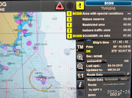
- Area with special conditions
An alarm or indication, as set by the user, will be given if, within a specified time or distance, own ship would cross the boundary of a geographic area for which special condition exists.
Although the ECDIS displays alarm options for several areas, IMO specifies the following areas for which an alarm or indication must be specified –
a) Traffic separation zone
b) Inshore traffic zone
c) Restricted area
d) Caution area
e) Offshore production area
f) Areas to be avoided
g) User defined areas to be avoided
h) Military practice area
i) Seaplane landing area
j) Submarine transit lane
k) Anchorage area
l) Marine farm/aquaculture
m) Particularly Sensitive Sea Area (PSSA)
The Master must ensure that at least all the above mentioned areas have been selected on the ECDIS to generate an alarm or indication, considering the location of the vessel (Ocean passage / Coastal / Congested waters) and the watch level being maintained at that time.
- Deviation from route
An alarm will be given if the specified cross track limit for deviation from the planned
route is exceeded. Minimum Settings: To be determined by the Master after reviewing the passage for
proximity of navigational hazards.
- Positioning system failure
Navigating officers should be aware of the non-reliability of the GPS input to ECDIS. The ECDIS will provide an alarm to the OOW in case of a Positioning System failure. In such cases, the DR mode on the ECDIS must be used until the Positioning System failure is rectified. When in the DR mode, regular position fixing must be done on the ECDIS using the LOP function.
- Approach to critical point
An alarm will be given by the ECDIS when the ship reaches a specified time or distance, set by the OOW, in advance of a critical point on the planned route (e.g., waypoint pre-arrival alarm).
- Different geodetic datum
The positioning system and the SENC should be on the same geodetic datum. ECDIS should give an alarm if this is not the case. It is recommended to keep GPS in WGS-84 datum all the time.
- Malfunction of ECDIS
Similar to other electronic navigational equipment, ECDIS can fail, either outright or in a way that can give misleading information. The navigator shall transfer navigation to the back-up system.
- Default safety contour
a) If the mariner does not specify a safety contour, this will be set to 30 metres by default. If the safety contour specified by the mariner or the default 30 metres contour is not in the displayed SENC, the safety contour shown will default to the next deeper contour.
b) If the safety contour in use becomes unavailable due to a change in source data, the safety contour will change to the next deeper contour by default.
c) In each of the above cases, an indication will be provided.
- Information overscale
ECDIS will provide an indication if the information is displayed at a larger scale than that contained in the ENC.
- Larger scale ENC available
ECDIS will provide an indication if own ship’s position is covered by an ENC at a larger scale than that provided by the display.
- Different reference system
ECDIS and added navigational information use a common reference system normally referred to as Common Consistent Reference Point (CCRP). If this is not the case, an indication will be provided.
- No ENC available
If the area covered by the ECDIS display includes waters for which no ENC is available, at a scale appropriate for navigation, the areas representing those waters will carry an indication to the mariner to refer to the paper chart or to the RCDS mode of operation.
In areas, where ENC is not available, RNC may be used in conjunction with updated folio of paper chart only after obtaining office approval.
- Customized display
If information categories included in the Standard Display are removed to customize the display, this will be permanently indicated. Identification of categories which are removed from the Standard Display can be shown on demand. Indications displayed, or the identification of the categories removed will be type specific to the ECDIS.
- Route planning across safety contour
An automated route check will provide an indication to the mariner wherever the Safety Contour is crossed, during route planning.
- Route planning across specified area
An indication will be given if the mariner plans a route closer than a user-specified distance from the boundary of a prohibited area or a geographical area, for which, special conditions exist (as mentioned in point 2 above). An indication will also be given if the mariner plans a route closer than a user-specified distance from a point
object, such as, a fixed or floating aid to navigation or isolated danger.
- Crossing a danger in route monitoring mode
An indication will be given to the mariner, if, by continuing on its present course and speed, over a specified time or distance set by the mariner, own ship will pass closer than a user-specified distance from a danger (e.g., obstruction, wreck, rock, etc.) that is shallower than the OOW’s safety contour or an aid to navigation.
- System test failure
ECDIS is provided with means for automatically or manually carrying out on-board tests of major functions. In case of a failure, the test will display information to indicate which of the module(s) is at fault.
Refer to the Makers manual for procedure and frequency of testing.
- Isolated danger Mark:
Kept on during planning – This is to clearly see these dangers and avoid them during planning
Kept off during monitoring – This allows the mariner to clearly see the difference between a wreck/rock or an obstruction. Even when off the isolated danger will still be highlighted in the look-ahead con.
- Anti-Grounding Cone:
The anti-grounding cone safety frame covers the area that will be used by ECDIS for generation of anti-grounding alarm, area alert or navigational alarm based on the chart data analysis or the user set safety parameters.
Safety frame of the Anti-grounding tool may be of below types:
- Box shape (As Danger detection Vector)
- Cone shape (As Danger detection Sector)
The size of anti-grounding tool will depend upon manufacturer of ECDIS system in use.
Within the option provided by the manufacturer, Master should decide the optimum setting of size for particular passage or leg of voyage basis size, manoeuvrability and speed of the vessel, proximity of navigational hazards, position plotting frequency, etc.
Few models of ECDIS have both, the danger detection vector and danger detection sector. Vessels are advised to use the appropriate safety frame which covers maximum area as per above minimum settings.
- SCAMIN:
During voyage monitoring, the ECDIS must be operated at compilation scale, when appropriate scale ENCs are available. When O.O.W. zooms out to improve situational awareness, the ECDIS may indicate an underscale warning and may limit this operation to a certain scale factor. The O.O.W. must be conversant with the procedure for resetting to the ENC compilation scale, as soon as wider situational awareness has been established.
During planning phase,Navigator may use smaller scale charts or zooms away from compilation scale to manipulate waypoints, however, check and visual inspection for dangers should be carried out at a compilation scale. Where, the ECDIS allows the selection of SCAMIN off / on :
a) The system must be set to operate with SCAMIN OFF for appraisal, planning and review phase to ensure all information is seen
b) SCAMIN must be selected ON for execution and monitoring of the Voyage plan in order to reduce the effect of over-crowded display
CROSSING SAFETY CONTOURS/ DEPTH/ HEIGHT
a. The following 4 settings are available to the user for highlighting available depth.
i. Safety Contour
ii. Safety Depth
iii. Deep Contour
iv. Shallow Contour
i. Safety Contour: This is a user entered value based on the vessels dynamic draft + adequate safety allowance. The ECDIS software will choose the next available deeper depth contour and shade the areas of the chart below this contour depth in blue.
e.g.: If the safety contour value is set to 6m, the ECDIS will take the next deeper contour on that ENC (for example 10m). The colour of chart shade below 10m contour will change to blue.
Whilst in the route monitoring mode, an alarm will be activated when the look ahead watch vector crosses the safety contour:
a. This gives the mariner advance warning that the ship is approaching potentially dangerous shallow waters.
b. O.O.W. should check and assess the distance and time available to reach till adjacent artificial safety contour
c. It should be confirmed that the crossing safety contour was as expected and discussed during passage plan meeting
d. O.O.W. should inform Master.
e. Any note such as tidal window to cross that area should be checked and verified for compliance.
f. It should be confirmed that alarm feature is on for adjacent artificial safety contour and vessel is navigating clear from this line.
ii. Safety Depth: Most ENC cells contain same standard range of depth contours that are shown on paper charts (2m, 5m, 10m, 20m, 50m etc). This limits the effectiveness of Safety Contour feature.
As explained in the example for Safety contour, the ECDIS will highlight waters between 6m and 10m also as potentially dangerous.
In order to provide improved visualization, Safety depth setting is provided in the ECDIS. Any sounding with a value equal to or less than the Safety Depth value entered by the operator will be displayed in bold to make them prominent.
Accordingly the value of Safety depth should be same as the value of Safety contour setting.
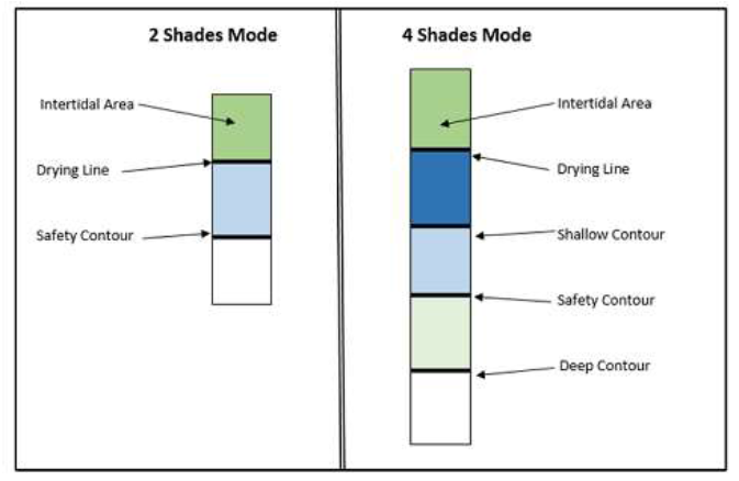
To allow more elaborate distinction of the depth areas, ECDIS has an option of choosing 2 colour shading or 4 colour shading. By default the 2 color shading will be set in the ECDIS.
In the 2 shade mode, all depth area with soundings less than the Safety contour will be blue and all sounding greater than the safety contour will be white/ black depending on the day-night mode settings.
In the 4 shade mode additionally 2 more contour setting values, i.e. Deep Contour and Shallow contour, influence the display.
iii. Deep Contour: This is user entered value that will affect the appearance of depth area beyond this value. The ECDIS software will choose the next available deeper depth contour and shade the areas of the chart beyond this contour depth in white/ black depending on the day-night settings.
iv. Shallow Contour: This is user entered value that will affect the appearance of depth area within the Safety contour. The ECDIS software will choose the next available deeper depth contour and shade the areas of the chart below this contour depth in dark blue.
So in the 4 shade mode, the area with depths lesser than the Shallow contour will become dark blue and the area between the Shallow contour and Safety contour will become light blue.
It is recommended the use of 4 shades mode during monitoring of the passage.
vi. Safety Height: This is a user defined value giving allowance for the vessels air draft. This feature warns the mariner in the planning stage, if the vessel will be passing under any structure (bridge, overhead wires etc.) with insufficient clearance.
CONFIGURING ECDIS FOR CROSSING SAFETY CONTOUR
a. Calculate safety depths and enter into ECDlS
b. Select viewing groups for soundings, seabed features and contours to be displayed
c. While running route check, if passage is found to be navigating safely through Safety contour, it will be required to draw an artificial safety contour.
d. Construct a manual update line to create an artificial Safety Contour equivalent to the safety depth, using the highlighted safety depth as an indication of the contour
e. Allow a safety margin where depth values displayed are less than the safety depth value.
f. Use existing contours to establish the likely shape of the manual contour
g. Set the manual update Line as an alarmed feature (refer to ECDlS manual and training course notes for guidance)
h. Run the route check facility to confirm that the feature will alarm
i. Ensure the plan is clear when the Safety Contour should be set to the artificial value and reset once the area is clear
j. Save as part of the Voyage Plan in ECDlS and note the feature in the Voyage Plan notes for review and approval by the Master.
k. The areas where vessel’s track is to navigate through Safety contour , should be mentioned in Passage plan and discussed in passage plan meeting.
l. If there is tidal window required to cross such area, same to be noted on ENC.
SETTINGS OF SAFETY CONTOUR AND SHALLOW CONTOUR
This is in line with publication NP232, following includes FAQ which will address doubts raised by inspectors/ auditors related to safety contour settings.
Mandatory ECDIS Alarms And Alarm Setting Guidance:
- Why Height of Tide is being subtracted from the Safety Contour depth? Why is it not added, as we do for depth calculation?
Let’s use an example to understand this.
Say, there is a position “X” on ENC with charted depth of 10 meters. As we move towards shore, there is another position “Y” on ENC with charted depth of 5 meters.
Now, assume that, Vessel’s dynamic draft + Minimum UKC requirement add up to 10 meters.
OOW would like to receive an alarm when vessel reaches 10 meters’ depth so that he is warned that beyond this limit, navigational safety is at risk. OOW will set Safety Contour depth in ECDIS as 10 meters. When vessel reaches position “X”, ECDIS will provide an alarm to OOW and OOW will take required action.
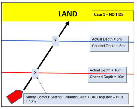
Above is the ideal situation.
Now, let us consider the case, in which the tidal range in that area is 5 meters.
Due to this tide of 5 meters, at high water, the actual depth in these positions will become:
Position “X” – 15 meters (Charted depth of 10m + 5 m tide)
Position “Y” – 10 meters (Charted depth of 5m + 5 m tide)
So, what should be the safety contour depth setting in this case?
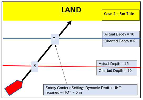
If we are going to keep it the same as before (i.e., 10 meters without considering the height of tide), OOW will get an alarm at position X (Charted depth -10 m) which is of no use. Because actual depth of water at “X” is now 15meters.
That is why, we subtract the Height of tide to revise safety contour depth setting as 5 meters i.e. Charted depth of 10 m – 5 m tide.
The OOW will now get an alarm at position “Y” (Charted depth of5m, actual depth due to tide of 10 m). OOW knows that Vessel is safe till position Y (of course, because of tide) and action is required to be taken when crossing position Y.
To put in a nutshell, OOW wants an alarm basis actual depth of water, while the ECDIS is to be set basis Charted depth. Hence, to get an alarmat any particular charted depth, OOW need to subtract the height of tide.
If OOW doesn’t subtract, the alarm will sound much earlier than needed, at 20 mts of actual depth (if we add the height of tide to the setting of safety contour setting, we will get the figure as 15 mts. The actual depth at the location will be 15 (charted depth) + 5 (HOT) = 20 mts).
- If height of tide is not subtracted, Vessel will get the alarm much in advance. What is the problem in erring on safer side?
Yes, you can say, there is no issue in erring on safer side. But then, your primary aim is to receive an alarm to remind you to act & not toignore. The Safety Contour is one of the most critical safety alarms used in ECDIS. Once this alarm is muted and ignored, there is no more alarm to warn OOW regarding inadequate depth.
Hence, it is important to set the depth alarm in such a way that when Safety contour alarm sounds, OOW takes it seriously and knows it’s time to act. That is why, to make best use of this alarm, it should not be set to static draft of vessel. It should be adjusted with all dynamic factors such as tide, squat, etc. and to make the error as minimum as possible.
- There will be areas with variable or unknown tide. How much tide to apply in that case?
Now that we know, height of tide is being subtracted to reduce the safety margin and make the safety contour depth as precise as possible.However, there will be areas where OOW is not very sure about height of tide.Let us understand this with similar situation as above example.
Say, Vessel is planning to call this port with tidal range between3 to 5 meters.
Hence, OOW’s first attempt should be to know the exact tide and subtract that value to get precise safety contour depth. If he is not sure ofexact tide, he will go to one extreme and apply either 3 or 5 meters and get following as safety contour depth at position X:
i) If he applies highest tide of 5meters, the safety contour depth at Position “X” will be set at 5 metres (Dynamic draft & net UKC requirement of 10m – HOT of 5 m tide)
ii) If he applies lowest tide of 3meters, the safety contour depth at Position “X” will be set at 7 metres (Dynamic draft & net UKC requirement of 10m – HOT of 3 m tide)
Now, setting of Safety Contour of 7 meters by taking lower of the tidal range , vessel will get the alarm when actual depth is 10 metres even at the lowest tide (7 m + 3 m HOT) , whereas by setting contour of 5 m using higher of the tidal range , if, inadvertently, ship transits this area during low tide, she will only get an alarm at actual depth of 8 metres (5m + 3m HOT), by which time, she will already run aground.
What this ultimately means is that even when there is a uncertainty of depth, you have assumed it on the side of safety.
OOW must keep in mind that subtracting tide is like eating up from safety margin. Hence, it should be applied but only if absolutely sure of.
In Open sea, as it is, precision of safety contour depth is not that important, hence, better to use lowest astronomical tide of the voyage. Inport approaches, precision is definitely required to make best use of this alarm. Hence, in coastal waters/ restricted waters, etc., proper tide calculation to be done for time of transit and same to be subtracted.
However,if there is any confusion about the height of tide at a port and it is not possible to ascertain the actual height
of tide during vessel’s transit through that area, then the lesser height of tide should be used for the calculation of safety contour.
- Why is shallow contour marked as one contour less than safety contour. OOW will need to change more frequently?
Yes, there is no doubt that OOW will need to change the shallow contour depth setting in ECDIS as and when the contour interval changes.
But then, the shallow contour has been given separately in ECDIS from Safety contour for a purpose.
The concern is that whatever value we put, ECDIS takes nearest higher available contour in order to start showing the colour (to help identifying safe and unsafe depths at a glance) accordingly.
For example, if any ENC has contours at 5m, 10m, 15m depths, the Safety contour depth set at 8m, will automatically jump to 10m (Nearest higher value). If we set the shallow contour 7m or 6m, that will also jump to 10m.
So, in most of the cases, safety and shallow contour will overlap.Then what is the benefit of having a feature of shallow contour? That is why the best use of shallow contour should be made by always checking on ENC and setting it with value of one contour less than safety contour value.
In above example, OOW should manually set the value of shallow contour as 5m so that safety contour’s light blue colour shows at 10 m contour and shallow contour dark blue colour shows at 5 m contour on ENC.
If we leave shallow contour as Dynamic draft, the difference between Shallow and safety contour will mostly be so indistinguishable that both the contours will overlap with each other and will be of little practical benefit.
OOW should know that Shallow contour is a complete “NO Go Area”.OOW should plan action immediately after crossing safety contour and much before shallow contour. Reaching till shallow contour should mean Vessel is either aground or going to be running aground shortly.
The contour depth intervals on different ENC can be 2m, 5m, 10m, etc. Hence, OOW should see that and set the shallow contour depth value as one less than safety contour depth setting.
MARKINGS ON THE ENC
ENC allows navigating officer to insert additional information using ‘Navigator’s Notes’ or ‘Mariner’s Information Overlays (MIO). Such facility allows the placing of text notes, any symbols in the presentation library or simple lines / areas with or without colour fill. The presence of a text note will be identified in the chart area at the defined
geographical p oint by a ‘!’ or ‘i’.
ECDIS SYSTEM MANAGEMENT & MAINTENANCE
Master should refer to the manufacturer’s instructions when handling ECDIS failures and malfunction. Instructions / procedures from maker’s manual should be kept handy for dealing with failures.
Vessels should maintain adequate spares on board as ECDIS is listed under critical equipment. Minimum spares to be maintained on board in consultation with manufacturer’s instructions. On board PMS system includes routine maintenance on ECDIS and the job instructions to be updated as per manufacturer’s guidelines;
Compliance with PMS routines should be confirmed by Navigating Officer. Proper care of the ECDIS system is important to ensure safe navigation.
- ENCs are supplied to the vessels by DVD. These are subject to physical damage or degradation if not handled or stored correctly. The latest DVD should be stored safely.
- When a voyage is planned, all courses, safety contours, waypoints and notes are saved in the system and stored in the voyage or routes sub folder for use again if the voyage is repeated.
- The system needs to be upgraded regularly; temporary files need to be deleted or old log files need to be cleared out as per manufacturer’s guidance to avoid clogging up the system and slowing down the operation.
- Vessels should only use a dedicated memory stick for transferring latest updates to ECDIS. There is still the possibility of virus attacks, therefore updates shall be applied to one ECDIS Console and updating of the second ECDIS should not be done unless the update results are verified on first ECDIS. It is suggested to update the back up
ECDIS first. Once it is successful, primary ECDIS shall be updated. - The navigating officer shall ensure that a back-up of the voyage plan on the ECDIS is available in case of equipment failure of the ECDIS itself or the connected sensors.
- Password Management (As applicable to the make/ model of ECDIS) : User password allows the navigator to make minor setup changes (non-critical) to ECDIS and this password shall be known to all navigating officers. Administration password permits user to make critical set up changes and shall only be accessed by the Master. Administration password shall be included in Master’s handing over notes.
- ECDIS will give audio-visual alarm to the duty officer in the event of breach of set values, the audio setting should NEVER be put to MUTE. Each time alarm is activated it should be acknowledged, problem verified and necessary corrective action taken.
- Master should ensure that after each service or attendance by the technician, it is confirmed that ECDIS settings have been restored and all the parameters/sensor inputs have been verified and tested. In case ECDIS undergoes significant change which impacts the feature and operation of the equipment, the attending technician
should explain the changes to the bridge team. - Master to ensure that ECDIS is checked on an annual basis and after every software upgrade for availability of Presentation Library 4.0 and same shall be recorded in Phoenix PMS. Any discrepancies should be reported to IHO as per requirements. In case the IHO check data set was not completed to satisfaction, then it should be reported to company for requesting a software upgrade.
- Master to ensure the ECDIS is always maintained to latest software version (compliant with IHO standards) at all times. Company will provide the list of software versions applicable to concerned models of ECDIS, latest IHO Standards,
USE OF ECDIS IN RCDS MODE
All navigable waters are not yet covered by ENC data and vessel may be required to use ECDIS in Raster Chart Display System (RCDS) mode using ARCS / approved raster charts.
If suitable ENC charts are not available from any source, then the use of raster charts is accepted only in conjunction with updated folio of paper charts with office approval. The following alarms and indications are required for an ECDIS operating in RCDS mode:
- ECDIS operating in raster mode
- Deviation from route
- Position system failure
- Approach to critical point
- Different geodetic datum
- Malfunction of RCDS mode
- Large-scale RNC available for ship’s position
Following precautions shall be taken while using raster charts:
- At the time of voyage planning, it is important that survey notes are carefully checked.
- The navigator should not alter WGS84 datum on the GPS to match that of the raster chart as required position transfer is automatically carried out by the ECDIS software.
- The navigator should be aware that raster charts do not generate automatic warnings of potential hazards. The displayed data is merely a digital copy of the original paper chart, the image has no intelligence and other than visually, cannot be interrogated.
PRECAUTIONS WHILE USING ECDIS
Following is the list of areas which need attention while using ECDIS:
- Errors of interpretations or human errors.
- Comparison of sound to noise ratio of the GPS system in use for input to ECDIS.
- Position shift (due to different datum between GPS and ECDIS) and reference shift (difference in the matching during superimposing of two displays).
- ECDIS position fixing system to be frequently checked by use of other means such as:
a. Parallel indexing and use of clearing bearings.
b. Use of Radar to check the accuracy of charted position by comparing the location
of identified radar target with chart symbol / object.
c. Visual cross bearings. - Ignoring scale of display.
- Uncritical acceptance of own ship position.
- Ignoring difference between True North and Gyro North.
- Confusion of different type of vectors, display mode and/or reference system.
- Source error; CATZOC.
- Object size error; the items on chart are not drawn to the scale.