How CO2 extinguishes fire
At atmospheric pressure carbon dioxide is a colouless, odourless and non-conductive gas that can quickly and thoroughly permeate a protected area, reduce the oxygen to a level below 15%, where combustion is not supported and extinct the fire.
CO2 extinguishes the fire by:
Reducing the oxygen level – The primary effect of CO2 is to lower the oxygen level within a risk from 21% to a level below 15%
Most fires are unable to exist in an atmosphere where the oxygen level has been reduced to 15% although some fires will require a further reduction in oxygen level to ensure extinction.
CO2 gas is approximately one and half times as dense as air the density at 1 bar and 21°C being 1.8 kg/m³.
Permeating the protected area (engine room , pumproom etc)
Carbon dioxide (CO2) gas has a high ratio of expansion which facilitates rapid discharge and allows for three dimensional penetration of the entire hazard area quickly.
Carbon dioxide is 1.5 times heavier than air and it quickly and effectively permeates the protected hazard are and suppresses the fire.
Providing Cooling effect
The secondary mechanism by which CO2 extinguishes fire is through cooling.
This effect is experienced as it absorbs heat and becomes vapour after leaving the discharge nozzles as liquid.
System components
Control Station
The means of control of fixed gas fire extinguishing system is readily accessible and simple to operate and is grouped together in as few locations as possible at positions not likely to be cut off by a fire in a protected space.
There are at least two locations where the CO2 release controls are provided,
⦁ One of which is at the storage location (CO2 room)
⦁ While the other is at a readily accessible location outside the protected space (fire control station)
At each location there is clear instructions relating to the operation of the system having regard to the safety of personnel.
⦁ Pilot Cylinder
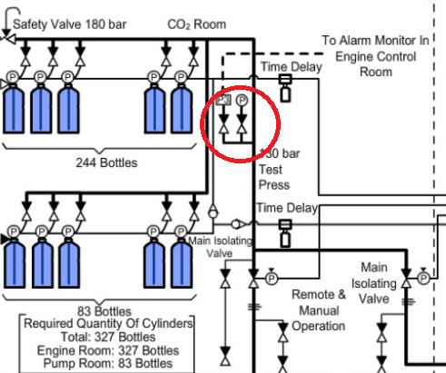
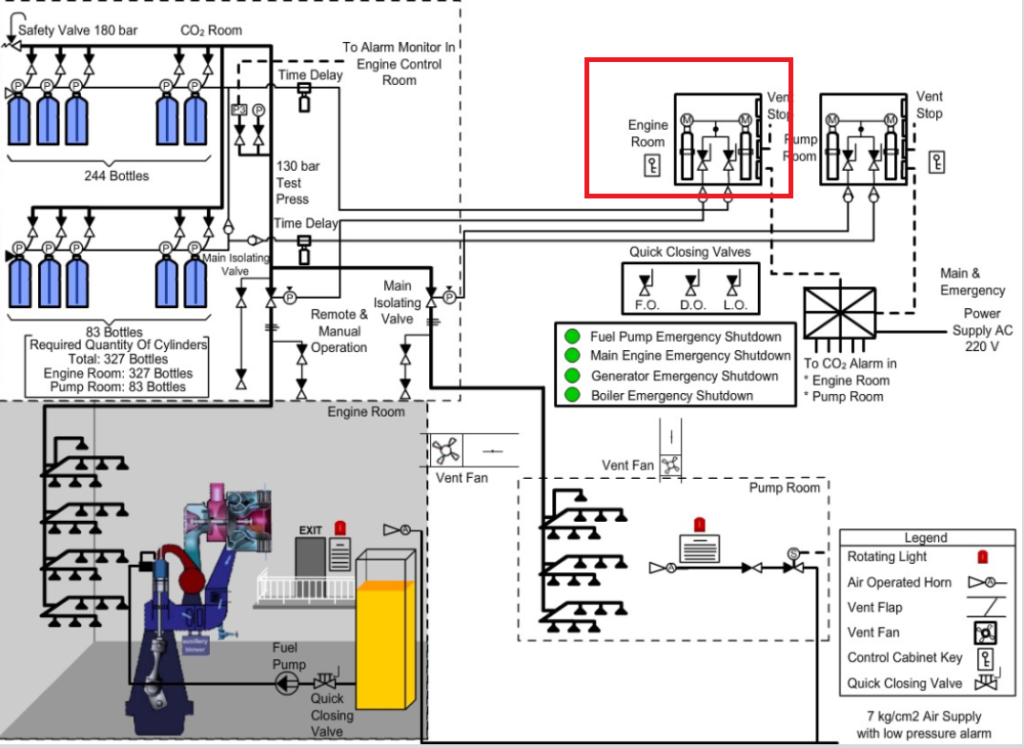
CO2 from the main bottle is released by a co2 release cabinet as shown in the figure. The control cabinet is locked and the key is available in break glass type enclosure located adjacent to the cabinet.
CO2 release cabinet or release box consist of two pilot CO2 cylinders or bottles containing CO2 gas inside.
The pressure of CO2 inside these pilot bottles is same as that of main CO2 bottles. Only quantity of gas is different.
For releasing CO2 to the protected space, one of the pilot bottle valve is opened. NOW CO2 reaches two separate control valves as shown below .
First valve 1 is to be opened. Then CO2 passes through a non return valve and opens pneumatically operated master valve.
Next, open valve 2 in the release cabinet, which supply CO2 to battery of main CO2 bottles head assembly through a non return valve and time delay unit. This action releases the battery of CO2 to protected space.
Main CO2 bottles are shared for engine room and pump room according to the volume of the spaces.
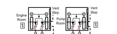
CO2 Alarm
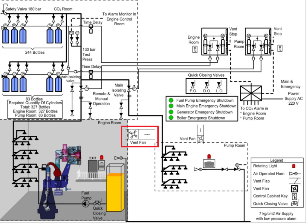
On opening the CO2 release cabinet, the alarm will sound and ventilation fans of the protected space will stop.
Power supply monitor
Should the system power supply fail, the CO2 power failure alarm will operate in the control room.
Time Delay
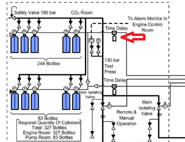
Means are provided for automatically giving audible warning of the release of CO2 into any space in which personnel normally work or to which they have access.
The alarm operates for a suitable period before the CO2 is released for personnel to vacate the protected space.
This achieved by incorporating a 20 to 30 seconds time delay, which may be electronic or pneumatic.
This extra time allows personnel to get out of the discharge area. It also allows additional time for ventilation and equipment shutdown.
The time delay is equipped with a manual override lever. This lever allows the time delay to be bypassed and allows the CO2 to discharge immediately.
Pressure Monitoring
Should any cylinder discharge accidentally it will pressurize the main line up to the stop valve. This line is monitored by a pressure switch which will activate the CO2 alarms.
CO2 Room
Co2 is stored outside a protected space, in a well ventilated readily accessible room.
Entrance to CO2 room is from the open deck.
Access doors open outwards, and bulkheads and decks including doors and other means or closing any opening therein, which from the boundaries between such rooms and adjoining enclosed spaces are gastight.
Independent mechanical ventilation system designed to take exhaust air from the bottom of the space is provided with capacity of at least 6 air changes per hour.
Means are provided for the crew to safely check the quantity of CO2 in the cylinders.
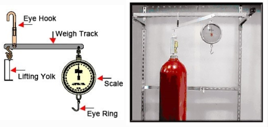
To use a weigh beam, the cylinders must be located in a cylinder rack with w weighing track attached. The flexible discharge bend must be removed from the cylinders to be weighed. The cylinder clamps should then be removed or loosened to allow the cylinders to move freely.
The operator lifts the cylinder by pulling down on the eye ring attached to the scale, The weight reading is then determined by reading the scale once the cylinder is stabilized with the weigh bar in the horizontal position as shown.
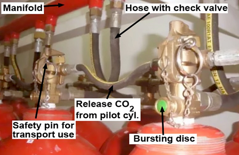
Flexible discharge bend
The flexible discharge bend is used to provide a flexible connection between the CO2 cylinder valve and the discharge piping or the distribution manifold.
The discharge bend has an internal check valve that prevents loss of agent should the system discharge while a cylinder is removed.
All flexible discharge bends are hydrostatically tested.
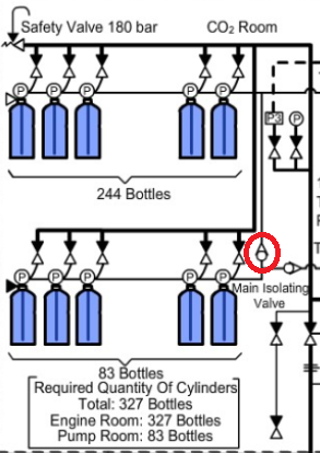
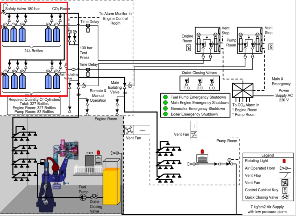
Main CO2 Bottles
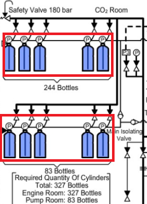
Main CO2 bottles contain 45kg of carbon dioxide in liquid state with a pressure of 56 bar at 20°C.
Pressure of CO2 at 25 and 30 degree Celsius are 64 bar and 71 bar respectively. So CO2 bottles should stored at temperature less than 55°C.

The busrting disc fitted on the CO2 bottles is designed to rupture spontaneously at 177 bar, which corresponds to temperature of 63°C.
The CO2 bottles can be fitted with either:
⦁ Manual/electric,
⦁ Manual/pneumatic actuator
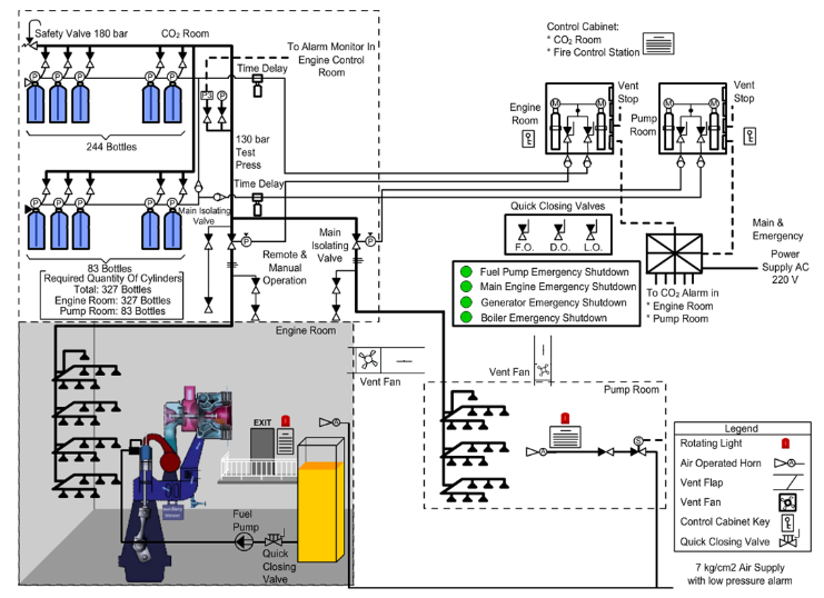
The CO2 flooding scheme shown here uses manual/ pneumatic actuator.
A number of CO2 bottles are connected to a manifold via non return valves to form a CO2 battery.
The serial number, gross weight, tare weight and date of manufacture are stamped on the CO2 bottles painted red.
Manual activation of individual CO2 bottle from CO2 room is done using the valve handle located CO2 room if remote CO2 pilot bottles fail to activate gang release of CO2 bottles battery.
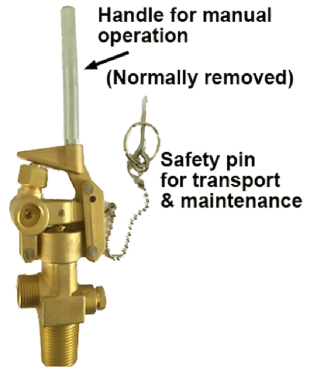
Safety pins on CO2 bottles are applied to prevent the unintended release of gas during maintenance & weight checking or for transportations purposes ashore.
However there are two types of CO2 cylinder head valves/actuators.
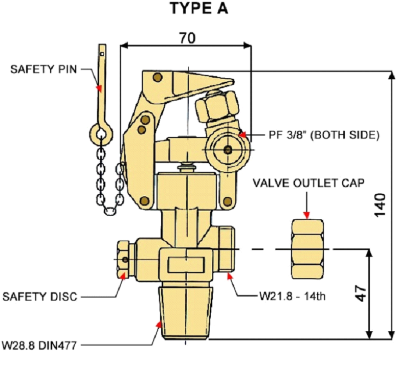
TYPE A
For type A cylinder valve, the safety pins acts as a safety device during transportation, installation and testing phases.
The pin must be removed to commission the system otherwise the CO2 system is inoperable.
TYPE B
For type B cylinder valve, the safety pin is necessary to prevent the unintended discharge of CO2 due to vibration and the pin is required to remain in place until discharge of the CO2.
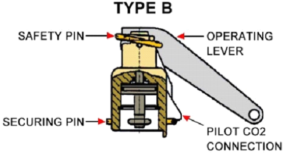
Where the CO2 is discharged remotely from a fire station, the CO2 can be discharged without removal of the safety pin.
Check Valve
Check valves are used to isolate the Engine room/ pump rom system supplies.
The valve prevents pressurization of the engine room system by blocking the flow of carbon dioxide from the pumproom system in the piping.
This allows a common piping and nozzle network to be utilized on engine room/ pump room application.
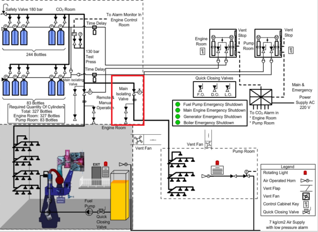
Main Isolating Valve (Master valve)
It provides the second step, stop valve function that helps to assure the safe release of CO2 in to the protected hazard.
As a selector valve, it directs the flow of CO2 into a engine room area when protecting multiple hazards (engine room & pumproom) with a common CO2 supply.
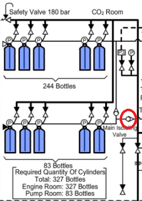
It is actuated by a remote pneumatic actuator valve and piping connection.
The main isolating valve is located near the carbon dioxide cylinders. Each valve has a flow direction arrow on the valve body that must point in the direction of flow to the engine room.
The valve is a differential pressure type that blocks the flow of agent until activated.
The valve can also be operated manually by operating the manual release lever located on top of the valve assembly.
Total flood nozzle
The radial nozzle is used for total flooding applications.
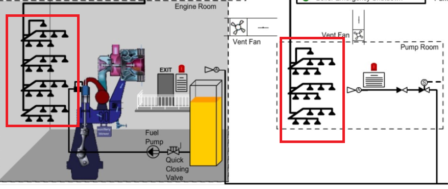
The nozzles can be located around the perimeter or in the center of the protected space.
The 3 orifice radial nozzle is designed for a 180° discharge pattern and the orifice radial nozzle is the 360° discharge pattern nozzle.
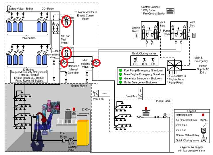
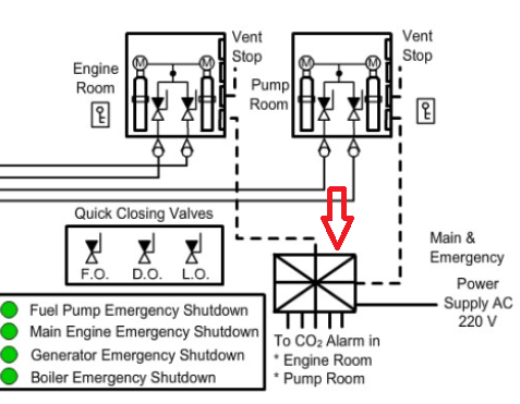
Audible alarms
Audible alarms are provided for automatically giving audible warning of the release of fire extinguishing medium into spaces in whihch personnel normally work or to which they have access.
The pre-discharge alarm is automatically activated e.g by opening of the release cabinet door. The alarm operates for the length of time needed to evacuate the space, but in no case less than 20 seconds before the CO2 is released.
Alarms may be pneumatically operated by CO2 or air, or electrically operated. If electrically operated. If electrically operated, the alarms are supplied with power from the main and an emergency source of power.
If pneumatically operated by air, the air supplied is dry and clean and the supply reservoir is fitted with a low pressure alarm. The air supply is taken from the starting air receivers. Any stop valve fitted in the air supply line is locked or sealed in the open position.
Any electrical components associated with the pneumatic system are powered from the main and an emergency source of electrical power.
Instructional Sign
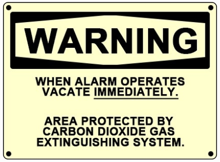
Instructional signs are provided to inform personnel of any potential hazards they face when operating certain devices or working within areas protected by CO2 systems. This warning sign is located throughout the protected space.
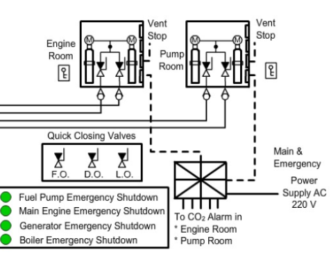
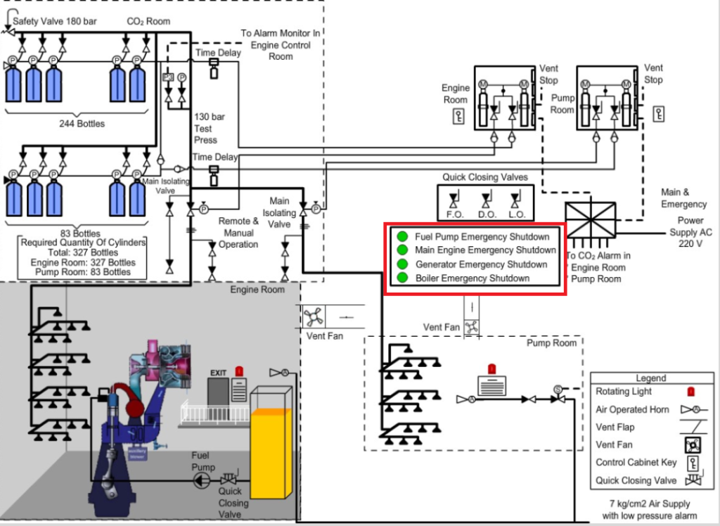
Emergency shutdowns
Oil fuel transfer pumps,
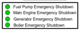
Oil fuel unit pumps, lubricating oil service pumps, thermal oil circulating pumps and oil separators and other similar fuel pumps, including stopping of fired equipment such as incinerator are shut down from outside machinery space in event of fire in engine room.
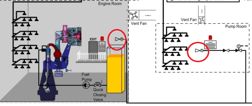
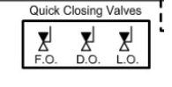
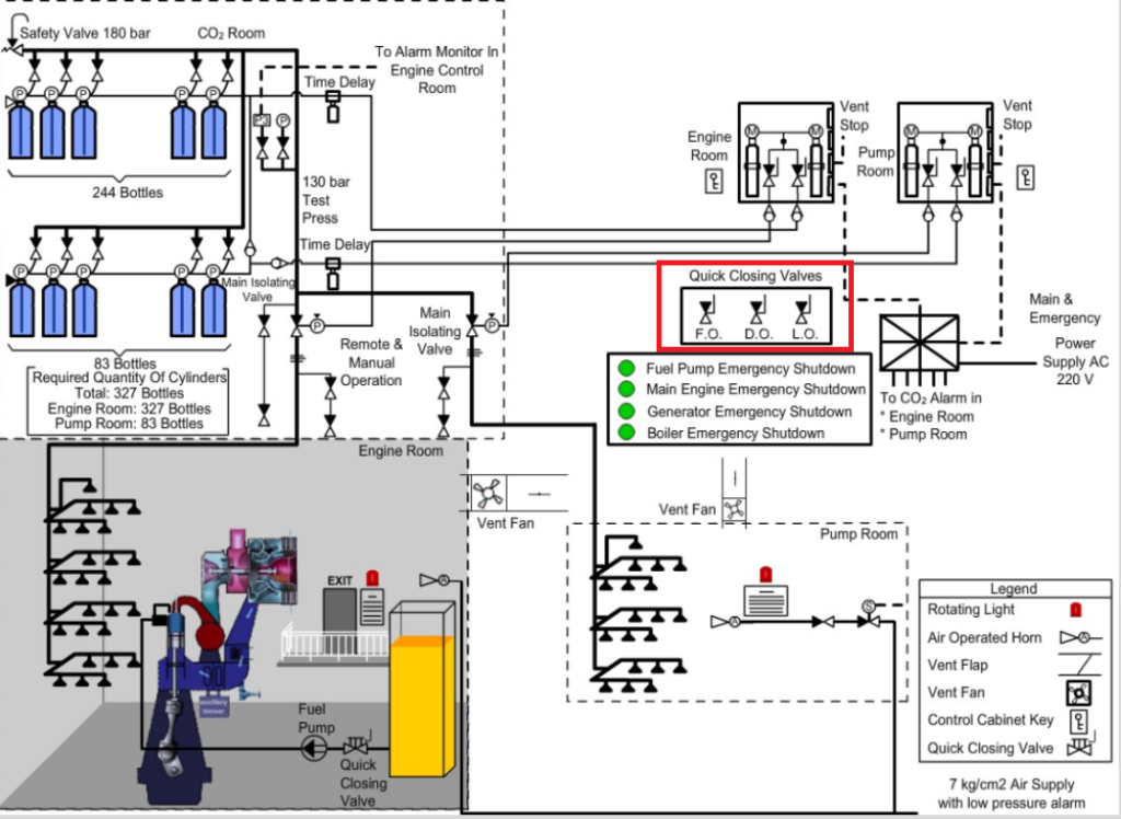
Quick closing of valves at fuel oil tanks and lubricating oil tanks
Remote quick –closing valves are installed at oil tank outlets so that they can be closed at a secure position to cut off the supply of oil that feeds an oil fire.
These valves can be closed locally or from a remote location (near fire control station) outside the engine room.
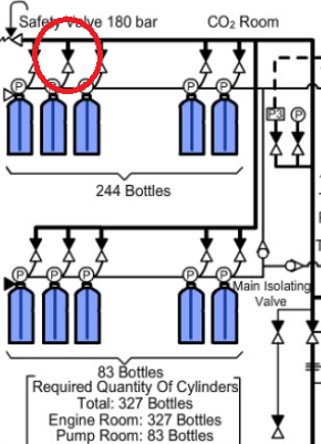
Manifold safety valve
There is a relief valve fitted in the manifold of CO2 flooding system. A pressure switch with alarm may also be fitted for CO2 leakage from any bottle.
Function of the relief valve is to release the CO2 pressure in the manifold to the free air (open air) outside CO2 room.
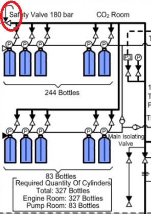
Such a situation arises when CO2 get released from the bottle and master valve is still closed. Set pressure of relief valve is about 180 bar. Again , set pressure varies with the system design and regulations.
These valves are actuated and closed along with fuel pumps and ventilation system before CO2 is released.
These valves must be tested regularly for remote operation as a part of routine maintenance.
A relief valve is required for two purposes:
a) If the pressure of fluid in a pipe line increases beyond the designed working pressure, there must be a pressure relief mechanism for bringing down the pressure to safe guard the system.
In the case of CO2 flooding system, CO2 will accumulate in the manifold when it si released from the bottle and master valve is closed.
Pressure of CO2 is 55 bar at 20 degree Celsius. As CO2 takes temperature from surroundings, its pressure also increases to dangerous levels.
Since these pipes are pressure tested to 190 bar only, a relief valve is necessary in the manifold.
b) Any pressure accumulate in the manifold may release other CO2 bottles which are intact, if the non-return valve between bottle and manifold is damaged.
Manual operation of CO2 System (Example for Engine room)
In the event of problem or failure of pilot cylinder, the CO2 can be released directly from the main cylinder bank installed in the CO2 room of the ship.
Follow the procedures as listed below:-
⦁ Ensure to sound CO2 alarm to warn personnel by opening the pilot control cabinet even if the CO2 pilot gas system is not operating.
This will also stop the ventilation fans.
⦁ Ensure no personnel is in the engine room, take attendance.
⦁ All Engine room Skylight and vent flaps are closed
⦁ Stop the fuel pumps and machineries from remote
⦁ Close the quick closing valves.
⦁ In the CO2 room, manually open the main isolating valve for Engine room.
First remove safety pin and turn the lever to open position.
⦁ Use actuating handle to manually open all CO2 cylinders applicable for Engine Room or manually open pilot cylinders in CO2 room which in turn would send pilot gas to remaining cylinders in the gang release system.
The CO2 will be discharged to the Engine room.
⦁ Know the system correctly and do not release the CO2 to any other space for example pump room.
⦁ Provide boundary cooling in Engine room
⦁ Do not re-open engine room for at least 24 hrs / Premature opening can cause re-ignition of combustible material
⦁ Maintain boundary inspections, noting cooling down rates and or any hot spots, which may have been found.
⦁ After this period, an assessment party donning breathing apparatus can enter the space quickly through a door, which is then shut behind them.
⦁ Check that the fire is extinguished and that all surfaces have cooled prior to ventilating the engine room.
⦁ Premature opening could cause re-ignition if oxygen contact hot combustible material
⦁ Do not enter the engine room without breathing apparatus until the engine room has been thoroughly ventilated, and the atmosphere proved safe, that is 21% oxygen content.
CO2 release procedures (Normal condition) (example engine room)
⦁ Go to the master control cabinet located at the CO2 room or fire control station.
⦁ Break the key box glass and take the key.
⦁ Unlock the cabinet and open the door (the micro switch will activate)
⦁ The rotating lights and air horns will operate in the engine room.
⦁ The engine room ventilation fans will stop.
⦁ Ensure that all personnel have evacuated the engine room spaces and have been accounted for.
⦁ Close all doors, hatches and shut fire flaps.
⦁ Stop the main engine, generating engines and boiler.
⦁ Operate the FO,DO and LO quick closing valves.
⦁ Open one pilot cylinder valve.
⦁ Open valve No.1 which opens the main isolation valve.
⦁ Open valve No.2 which operates the gang release system.
⦁ All cylinders will release after short time delay and discharge into the engine room.
⦁ Do not open the engine room for at least 24 hrs. Do not reopen the space until all reasonable precautions have been taken. Maintain boundary inspections, noting cooling down rates and/or any hot spots which may have been found. After this period, an assessment part donning breathing apparatus can enter the space quickly through a door which is then shut behind them. Check that the fire is extinguished and that all surfaces have cooled prior to ventilating the engine room. Premature opening could cause re-ignition if oxygen contacts hot combustible material.
⦁ Do not enter the engine room without breathing apparatus until the engine room has been thoroughly ventilated and the atmosphere proved safe i.e 21% oxygen content.