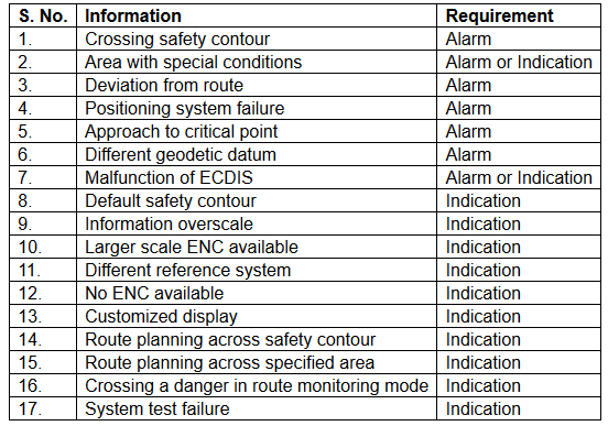
Below is the list of mandatory alarms / indication as per MSC Resolution 232(82).
Alarm: An alarm or alarm system which announces by audible means, or audible and visual means, a condition requiring attention.

Indicator: Visual indication giving information about the condition of a system or equipment.
When using ENCs, an alert will be given when charted hazards enter the safety domain, even if the hazard is not visible on the displayed portion of the ENC.
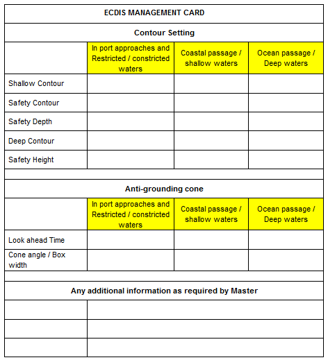
Alarms settings guidance for Ocean passage / Coastal / Congested waters as per company requirements and specific to ships draft, should be entered into the ECDIS Management card and posted at a visible location near the ECDIS.
Alarms settings are dynamic in nature and are to be regularly reviewed and updated as the voyage progresses from congested waters to open sea and vice versa. The Bridge team must be aware of the Alarm settings and the ENC should be adequately marked where the settings need to be changed. Alarm settings on the ECDIS must be done diligently so as to avoid unnecessary alarms and unwanted distraction to the officer on watch.
Alarms are to be set by the navigating officer at the time of passage planning and once the Master has reviewed the passage / alarm settings, they should be locked where such a facility is available
The alert will be an alarm or indication, depending on the circumstances and user settings. Alarms received in the ECDIS must be acknowledged and appropriate action to be taken to address the alarm as per the guidance given below.
- Crossing Safety Contours / Depth
There are generally three contour settings available to the user for highlighting available depth. The contours are differentiated by colours and if a guard zone touches the safety contour it will give an alarm. In case the contour for the value entered is not available on the ENC, the ECDIS will select the next available deeper contour by default.
a. Safety Contour: This is a user entered depth that ideally coincides with the contours, giving an adequate safety allowance for the dynamic draft of the vessel. This is the only contour that is required to generate an alarm upon crossing.
Deep and Shallow contours only provide display and are not required to generate any alarms.
b. Safety Depth: The spot soundings below the specified value entered for safety depth will appear bold. These are not required to generate any alarms.
When the vessels planned passage is within the Safety Contour these spot soundings provide a visual indication to the navigator and must be used to create No Go Areas using User Map Lines capable of generating an alarm.
Minimum Settings: Setting should be based on vessel’s dynamic draft.
Dynamic draft = Present maximum static draft + All allowances (Squat + Sinkage due to Density + Allowance for Sea State + Heel Correction + Seasonal variation + other allowances)
Following is the minimum value recommended by my Company.
Safety Contour = Dynamic draft+ Minimum Net UKC requirement – Height of tide
Safety Depth = Safety Contour
Shallow Contour = One Contour less than Safety Contour
Deep Contour = 50 meters.
Safety Height = Air draft of the vessel + 2 meters.
Note:
a) When navigating within a dredged channel where the limits of the dredged channel are drawn by contours on the ENC, these limits can be set as the Safety Contour. This will clearly demarcate the channel and avoid the need to mark any additional No-Go areas outside the dredged channel.
b) The Safety Depth setting should guide the mariner in setting up the No-go Areas. Therefore, the vessel should never go over a sounding equal or less than Safety Depth value (which will be emphasized). In the vicinity of the route these must be marked as No-Go (as artificial contour) using the Danger line (available in user map).
c) The Shallow Contour should not overlap with the Safety Contour, i.e Dark blue and Light blue colours should be clearly visible.
d) CATZOC – As recommended by INTERTANKO ECDIS guidance, “The depth accuracy guidance found in NP100 does not require the accuracy values to be deducted from the charted depth but for the mariner to be aware of the likelihood of a different depth within the accuracy values.”
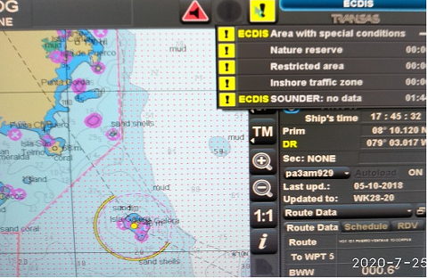
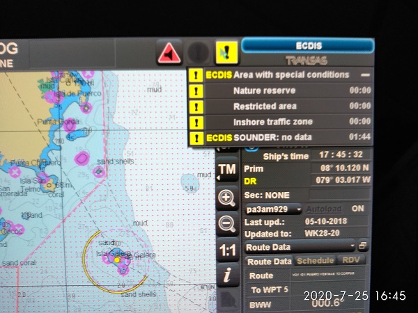
2. Area with special conditions
An alarm or indication, as set by the user, will be given if, within a specified time or distance, own ship would cross the boundary of a geographic area for which special condition exists.
Although the ECDIS displays alarm options for several areas, IMO specifies the following areas for which an alarm or indication must be specified –
a) Traffic separation zone
b) Inshore traffic zone
c) Restricted area
d) Caution area
e) Offshore production area
f) Areas to be avoided
g) User defined areas to be avoided
h) Military practice area
i) Seaplane landing area
j) Submarine transit lane
k) Anchorage area
l) Marine farm/aquaculture
m) Particularly Sensitive Sea Area (PSSA)
The Master must ensure that at least all the above mentioned areas have been selected on the ECDIS to generate an alarm or indication, considering the location of the vessel (Ocean passage / Coastal / Congested waters) and the watch level being maintained at that time.
3. Deviation from route
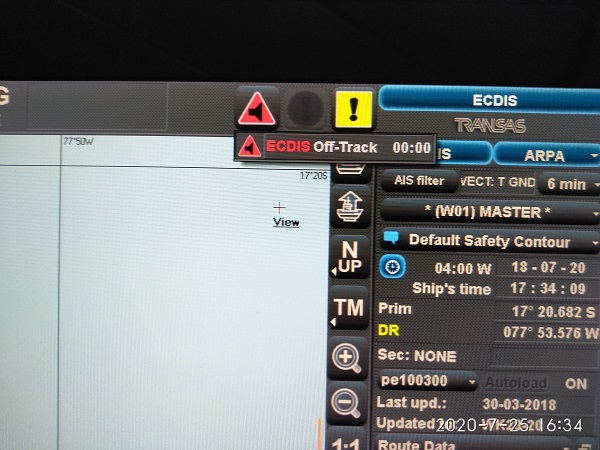
An alarm will be given if the specified cross track limit for deviation from the planned route is exceeded.
Minimum Settings: To be determined by the Master after reviewing the passage for proximity of navigational hazards.
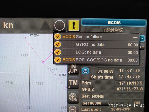
4. Positioning system failure
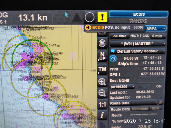
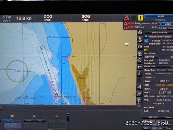
Navigating officers should be aware of the non-reliability of the GPS input to ECDIS. The ECDIS will provide an alarm to the OOW in case of a Positioning System failure. In such cases, the DR mode on the ECDIS must be used until the Positioning System failure is rectified. When in the DR mode, regular position fixing must be done on the ECDIS using the LOP function.
5. Approach to critical point
An alarm will be given by the ECDIS when the ship reaches a specified time or distance, set by the OOW, in advance of a critical point on the planned route (e.g., waypoint pre-arrival alarm).
6. Different geodetic datum
The positioning system and the SENC should be on the same geodetic datum. ECDIS should give an alarm if this is not the case.
It is recommended to keep GPS in WGS-84 datum all the time.
7. Malfunction of ECDIS
Similar to other electronic navigational equipment, ECDIS can fail, either outright or in a way that can give misleading information. The navigator shall transfer navigation to the back-up system.
8. Default safety contour
a) If the mariner does not specify a safety contour, this will be set to 30 metres by default. If the safety contour specified by the mariner or the default 30 metres contour is not in the displayed SENC, the safety contour shown will default to the next deeper contour.
b) If the safety contour in use becomes unavailable due to a change in source data, the safety contour will change to the next deeper contour by default.
c) In each of the above cases, an indication will be provided.
- Information overscale
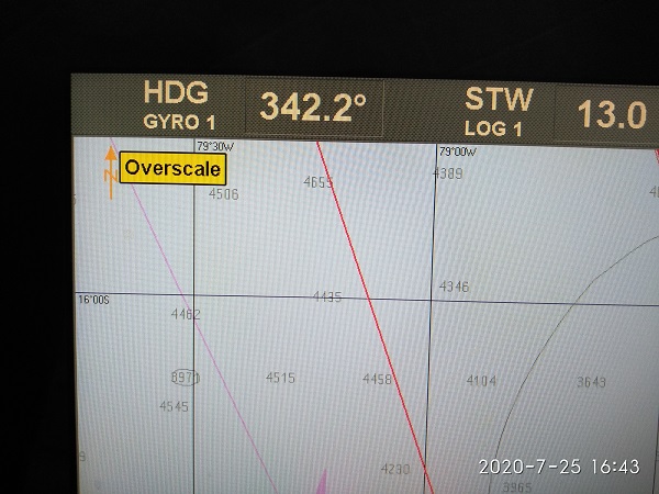
ECDIS will provide an indication if the information is displayed at a larger scale than that contained in the ENC.
- Larger scale ENC available
ECDIS will provide an indication if own ship’s position is covered by an ENC at a larger scale than that provided by the display.
- Different reference system
ECDIS and added navigational information use a common reference system normally referred to as Common Consistent Reference Point (CCRP). If this is not the case, an indication will be provided.
- No ENC available
If the area covered by the ECDIS display includes waters for which no ENC is available, at a scale appropriate for navigation, the areas representing those waters will carry an indication to the mariner to refer to the paper chart or to the RCDS mode of operation.
In areas, where ENC is not available, RNC may be used in conjunction with updated folio of paper chart only after obtaining office approval.
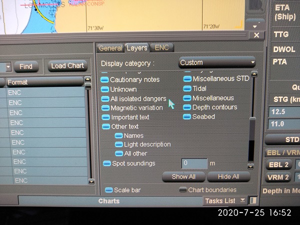
- Customized display
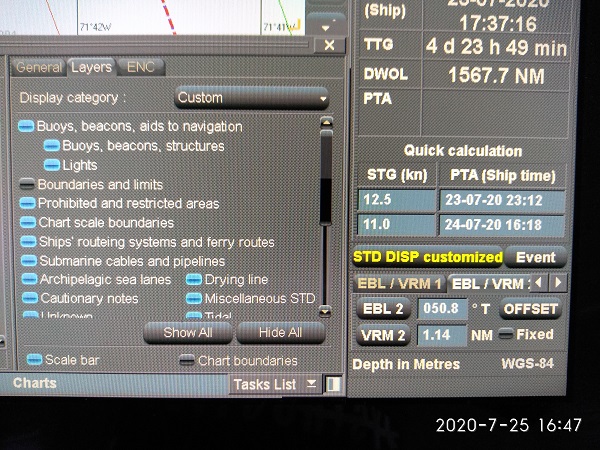
If information categories included in the Standard Display are removed to customize the display, this will be permanently indicated. Identification of categories which are removed from the Standard Display can be shown on demand. Indications displayed, or the identification of the categories removed will be type specific to the ECDIS.
- Route planning across safety contour
An automated route check will provide an indication to the mariner wherever the Safety Contour is crossed, during route planning.
- Route planning across specified area
An indication will be given if the mariner plans a route closer than a user-specified distance from the boundary of a prohibited area or a geographical area, for which, special conditions exist (as mentioned in point 2 above). An indication will also be given if the mariner plans a route closer than a user-specified distance from a point object, such as, a fixed or floating aid to navigation or isolated danger.
- Crossing a danger in route monitoring mode
An indication will be given to the mariner, if, by continuing on its present course and speed, over a specified time or distance set by the mariner, own ship will pass closer than a user-specified distance from a danger (e.g., obstruction, wreck, rock, etc.) that is shallower than the OOW’s safety contour or an aid to navigation.
- System test failure
ECDIS is provided with means for automatically or manually carrying out on-board tests of major functions. In case of a failure, the test will display information to indicate which of the module(s) is at fault.
Refer to the Makers manual for procedure and frequency of testing.
- Isolated danger Mark:
Kept on during planning – This is to clearly see these dangers and avoid them during planning
Kept off during monitoring – This allows the mariner to clearly see the difference between a wreck/rock or an obstruction. Even when off the isolated danger will still be highlighted in the look-ahead con.
- Anti-Grounding Cone:
The anti-grounding cone safety frame covers the area that will be used by ECDIS for generation of anti-grounding alarm, area alert or navigational alarm based on the chart data analysis or the user set safety parameters.

Safety frame of the Anti-grounding tool may be of below types:
1. Box shape (As Danger detection Vector)
2. Cone shape (As Danger detection Sector)
The size of anti-grounding tool will depend upon manufacturer of ECDIS system in use.
Within the option provided by the manufacturer, Master should decide the optimum setting of size for particular passage or leg of voyage basis size, manoeuvrability and speed of the vessel, proximity of navigational hazards, position plotting frequency, etc.
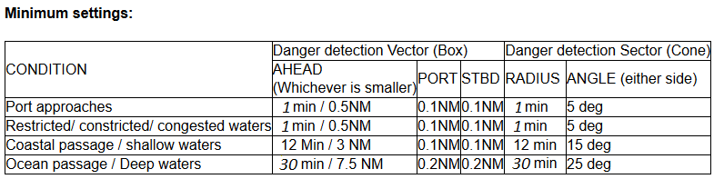
Few models of ECDIS have both, the danger detection vector and danger detection sector. Vessels are advised to use the appropriate safety frame which covers maximum area as per above minimum settings.
The minimum settings mentioned above are company recommendations. However, master may use anti-grounding tool settings higher than the company’s minimum requirements, appropriate to the prevailing circumstances. Also, the limitation of option provided by the manufacturer has to be borne in mind.
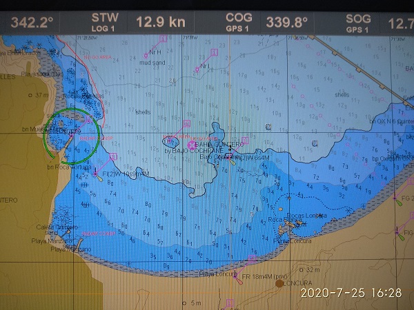
- SCAMIN:
During voyage monitoring, the ECDIS must be operated at compilation scale, when appropriate scale ENCs are available. When O.O.W. zooms out to improve situational awareness, the ECDIS may indicate an underscale warning and may limit this operation to a certain scale factor. The O.O.W. must be conversant with the procedure for resetting to the ENC compilation scale, as soon as wider situational awareness has been established
During planning phase,Navigator may use smaller scale charts or zooms away from compilation scale to manipulate waypoints, however, check and visual inspection for dangers should be carried out at a compilation scale.
Where, the ECDIS allows the selection of SCAMIN off / on :
a) The system must be set to operate with SCAMIN OFF for appraisal, planning and review phase to ensure all information is seen
Display showing where SCAMIN is switched off!!!
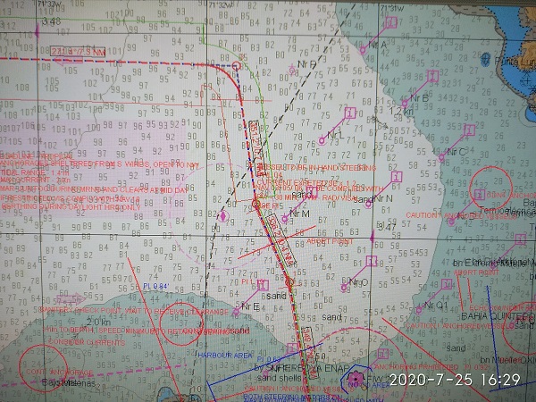
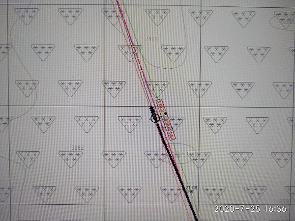
b) SCAMIN must be selected ON for execution and monitoring of the Voyage plan in order to reduce the effect of over-crowded display
Display showing where SCAMIN is switched ON!!!