The inert gas system (IGS) consists of a main inert gas plant, using boiler flue gas to provide a gas explosion protection system, i.e. a low O2 content in the cargo oil tanks and slop tanks. This is achieved by maintaining a slight overpressure in the tanks at all times.
Whilst discharging the cargo, liquid pumped out of the tanks is replaced by inert gas. At all times, pressure of the inert gas in the tanks is to be maintained above atmospheric pressure.
The IG used on this vessel is produced by a conventional flue gas plant, which cools and cleans exhaust gas from the boiler uptake. The resulting exhaust gas is then fed into the cargo tanks via a deck seal. The system is designed to maintain a positive tank pressure whilst the vessel is discharging using all cargo pumps at maximum rate, with a tank O2 content of less than 5% maximum.
The system is used during:
• Cargo oil unloading
• Purging the AUS vacuum pump and lines during discharge operations when the AUS is in line
• Hydrocarbon gas purging
• Tank cleaning
• Crude oil washing
• Reducing the O2 content in the tank volume
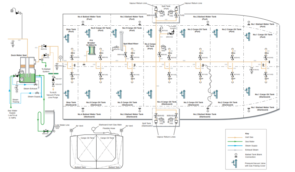
• Emergency inerting from deck of the ballast tanks via a dedicated flexible hose.
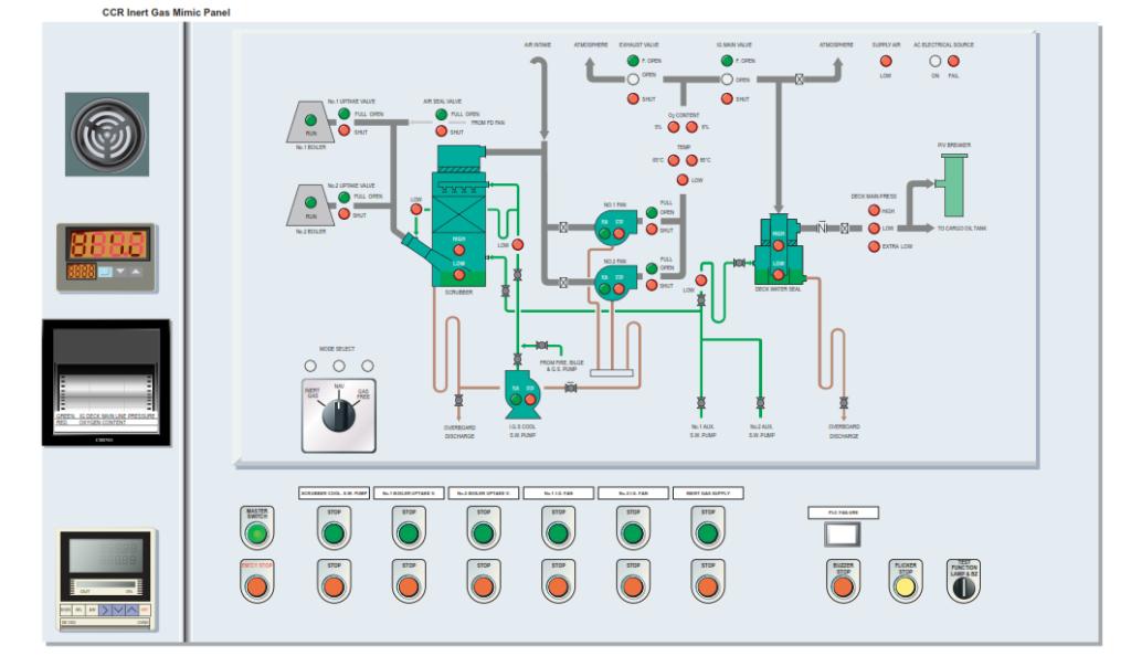
Main Inert Gas System
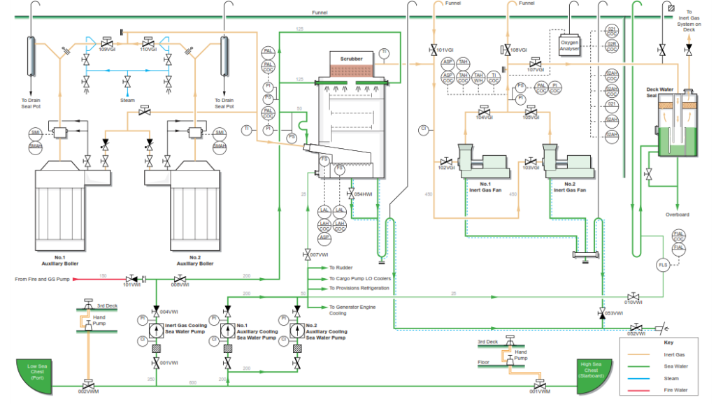
The flue gas from the boiler uptake is led into a scrubber tower which cools and cleans the exhaust gas before the gas is distributed by an IG fan to the cargo oil and slop tanks via a deck water seal non return valve and distribution piping. The system is used to purge the ullage spaces in the cargo oil tanks of hydrocarbon gases and replace them with an inert gas, keeping the oxygencontent below 5% by volume.
When the boilers are operating efficiently, the composition of the inert gas byvolume should be:
Carbon dioxide: approximately 13.0%
Oxygen (O2): approximately 3.0%
Sulphur dioxide (SO2) : < 0.03%
Nitrogen (N): Balance
However, during low boiler load operation, the oxygen content of the boiler exhaust gas will tend to rise due to the higher excess air required for good combustion. To overcome this the boiler is set to a minimum load setting of approximately 20%. This is in order to ensure that the load on the boiler is sufficient to maintain the oxygen content level at approximately 3%. Any excess steam that cannot be used will be dumped to the vacuum condenser, its is essential that the vacuum condenser is in full operation condition before steam dumping is carried out.
CAUTION : When running with the boiler on low load, it is possible that the IG flue gas fan may draw air down the boiler funnel uptake resulting in an out of range O2 acceptability.
Scrubber
The scrubber is of the tower type and consists of inlet water seal tanks, tower elements and spray nozzles.
The purpose of the scrubber unit is to cool the exhaust gas, remove soot particles and sulphur and sulphur dioxide from the exhaust gases drawn from the boilers and therefore produce a ‘clean’ inert gas.
Hot flue gases are drawn from the boiler uptake and accelerated through the inlet venturi tube where they are sprayed with sea water. In this stage, the gases are pre-washed and cooled to between 60 and 70°C.
The gases are deflected up the tower through the packed wet filter, providing further cooling and cleaning. The gas then passes into the open spray tower, which is the final cooling process. The water mist is highly efficient in removing sulphur. The spray also assists in maintaining the wet filter in a clean condition by a continuous flushing action. The gas at this stage is cooled to atmospheric temperature plus 5C. The clean cool gas passes through a mesh demister in the top of the scrubber tower which prevents water droplets from being carried over with the outlet gas flow.
An independent cooling sea water supply pump supplies the scrubber.
Emergency cooling water can be supplied to the scrubber unit from either of the fire and bilge or fire and GS pumps. The water leaving the scrubber is directed via a discharge line which incorporates a ‘U’ bend seal directly overboard.
Inert Gas Fans
Two electrically driven inert gas fans are supplied. Each is capable of supplying the full rated inert gas. They draw the gas from the boiler uptake, through the scrubber and deliver to the deck distribution pipe system via the deck water seal with sufficient overpressure to form a high velocity gas et at the inlet to the cargo tanks.
The blower casing of each fan is provided with water washing spray nozzles and drains. The washing system is manual so that after the fans are stopped, a hose is connected up and fresh water is injected onto the fan impellor via three nozzles in order to clear away any soot particles.
Deck Water Seal
The deck water seal is of the displacement type. The water inside the seal is displaced into a reservoir during operation, and immediately falls back and closes the seal in case of loss of positive gas pressure, preventing any back- flow of cargo gases.
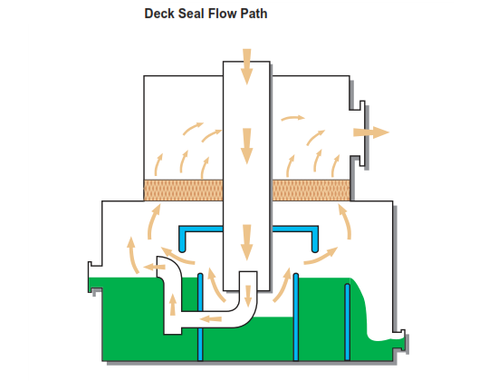
The deck water seal is gas leakage proof, due to an internal double seal pipe forming two gas barriers. The water seal has a built-in heating coil for use in cold weather conditions. Additionally, the sea water supply line is lagged and fitted with a trace heating pipe to ensure the flow into the seal is maintained during freezing weather conditions.
The mesh demister in the upper part of the seal prevents carry-over of water droplets under all flow conditions.
In the event of a loss of IG delivery gas pressure, the water immediately falls back and closes the seal, thereby preventing any back-flow of gases to the boilers in the engine room.
Any back pressure from the cargo tank area will induce an overpressure in the reservoir chamber above the water level and force water into the centre tube.
The water level in the centre tube will rise and thus prevent gas from leaking past the seal. An externally mounted sight glass is provided, enabling the level of the seal water within the chamber to be checked.
A seal water flow alarm is fitted in the sea water supply line, which initiates a low flow alarm. The deck seal chamber is also fitted with a high and low level alarm float switches. Overfilling of the deck water seal is prevented by a weir and direct overboard discharge. The deck seal is constantly supplied with sea water branched off from the engine room auxiliary sea water system, the standby pump is set to automatic should the running pump fail.
Pressure/Vacuum Breaker
A pressure/vacuum breaker is fitted to the inert gas line on deck . The breaker is filled with a mixture of antifreeze (glycol) and water and will open at a preset pressure or vacuum, thus protecting thetanks against too high a pressure or vacuum.
There is a sight glass fitted to the side of the PV breakers, the level of which should be checked before cargo operations. The correct mixture of antifreeze is 75% fresh water to 25% ethylene glycol.
Periodically it will be necessary to check the levels inside the breaker, both for the inner and outer tube areas. The sight glass level gauge on the side of the breaker body is used for this purpose and is fitted with two gauge scales.
Flue Gas Isolating Valves
As the flue gas isolating valves are subject to high temperature variations they are therefore not gas tight in the closed condition. Gas leakage into the system is prevented by the automatic provision of air sealing from the boiler FD fan when the flue gas system is shut down and the boiler is operating.
A manually operated valve is mounted close to each boiler uptake duct for soot cleaning on the boiler side of the flue gas isolating valve; steam for this operation comes from the low pressure service steam system. Double acting cylinders, controlled by solenoid valves, pneumatically operate the master uptake valves. These flue gas isolating valves should be steam blasted for a short period before flue gas is directed into the inert gas system. Additionally, steam blowing should be carried out after cargo IG operations have been completed in order to clean the faces of the valve.
Sealing Air Valve
To prevent boiler flue gas leaking past the boiler uptake valves when the plant is shut down, a sealing air supply line is fitted. This runs from the discharge side of the boiler forced draught fan to the pipeline between the boiler flue gas isolating valve and the downstream main valve. When the boiler uptake valves are open, the sealing air pneumatic piston operated valve is closed and vice versa.
Flow Control Valves
Butterfly control valves operated by pneumatic actuators, will control the flow through the system. To protect the blower motor, the valves are held in the closed position during the blower start-up period.
Blow Off Valve
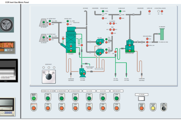
A butterfly valve is provided for gas venting, it is pneumatically operated and used to control the discharge pressure onto the inert gas main, the pressure setting control panel is mounted on the IG control panel in the CCR. When level is within operational limits and the INERT GAS SUPPLY ‘Start’ control button is pressed, the delivery valve to the IG main, and the vent to atmosphere valve will be modulated according to the pressure setting on the control panel.
When the O2 value goes out of range, the vent to atmosphere is automatically opened and the delivery to deck is shut.
When the plant is started with the blower running and the main deck line control valve closed, the blow off valve will open, relieving the gas from the blower outlet to atmosphere, thus preventing overheating of the running blower.
Oxygen Analyser
A fixed oxygen analyser is installed, which samples the inert gas after it has passed through the blowers. Prior to starting the IG plant, the oxygen analyser should be put into operation and the span tested approximately 15 minutes before the IG plant is started.
Inert Gas System Alarms and Trips
The following conditions give indication in the alarm system and cause the valves to go into a shutdown position and the plant to stop operating, but not the deck seal supply which will continue:
- Emergency stop
- Low instrument air pressure
- High sea water level high in scrubber
- Blower failure
- Low sea water supply pressure
- High IG outlet temperature from blower (65°C)
- Low sea water supply pressure to the scrubber – flue gas
- Low sea water supply pressure to the deck seal reservoir
The following conditions give indication in the alarm system and opening of the vent to atmosphere and closing of the main discharge line valve:
- High gas pressure in deck main line
- High oxygen content, vent to atmosphere will open (5%)
The following conditions give indication in the alarm system:
- Low and extra low deck IG pressure
- High and low sea water level in the deck seal
The following conditions give indication in the alarm system and a shutdown signal to the cargo pumps:
- Low low deck IG pressure 100mmWG