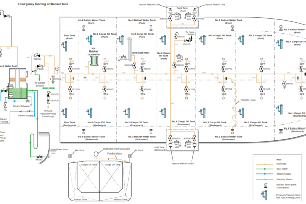
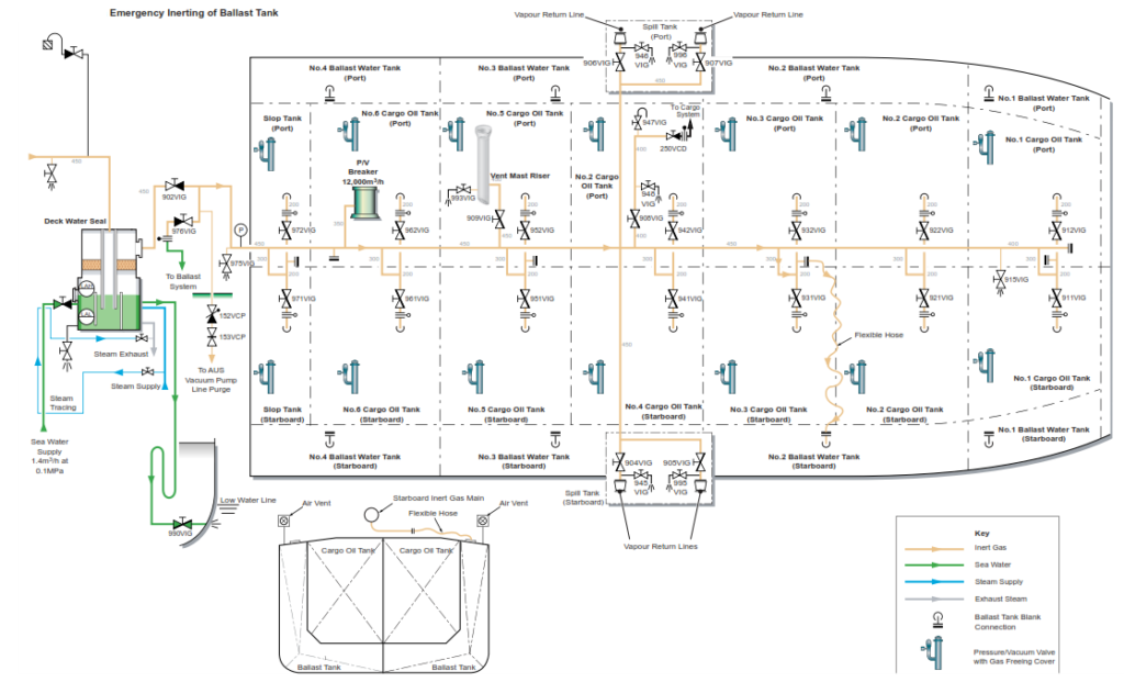
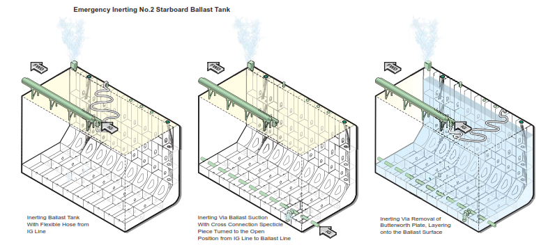
Opposite each ballast tank there is a spur pipe off the 200mm IG line to the cargo tanks, which is fitted with a blank flange, this is to facilitate the emergency inerting of the ballast tanks. One flexible hose, 150mm in diameter and 30m long and two portable bends are provided for inerting via a butterworth plate located on each ballast tank on deck. This system would be used if it is required to layer inert gas over the top of ballast. Alternatively, it is possible to direct IG into a ballast tank via its suction line, by connecting the IG main to the ballast line by the turning around the spectacle blank located at outboard and slightly forward of the entrance into the pump room on the port side. This system would be used if the ballast tank is empty.
Procedure to Carry Out Emergency Inerting of a Ballast Tank
(Example 1, No.2 Starboard Ballast Tank, No Flooding)
a) The inert gas plant should be ready for operation.
b) Turn the spectacle blank on the IG main to the ballast system, then open the open return valve . Open the ballast system line valves to No.2 starboard ballast tank as indicated below:
- Ballast pump(s) discharge to the overboard line
- No.2 ballast pump discharge to the overboard and eductor drive
- No.2 ballast pump discharge to the starboard ballast main
- No.2 starboard ballast tank suction/filling valve
c) Start up and run the IG system, normal operating parameters apply. Open the deck isolating valve
on the IG line. Inert gas will now be sent to No.2 starboard ballast tank.
d) Open the ballast tank hatch to act as a vent, provided that there is no lightning or source of ignition in the vicinity.
e) Monitor the vapour at the outlet.
The atmosphere from the ballast tank should be vented via the tank hatch for the three possible alternatives of inerting the tanks. The pressure in the ballast tank can be controlled by the IG to deck pressure setting regulator and also by the IG line master controller to the mast riser.
Continue inerting until the oxygen reading at the sample point is consistently below 8%. Depending on requirements, it is prudent to continue inerting until a level of 5% or less oxygen is reached, to give a greater safety margin.
If the ballast tank is partially flooded, connect the flexible hose from the adjacent spur off the ballast main to the connection point on the ballast tank. As there is less volume to fill, it is essential to monitor the pressure and IG flow rate into the tank.
Example 2, to Carry Out Emergency Inerting of No.2 Ballast
Tank Starboard with the Partially Tank Flooded
a) Check that the COT IG pressure has been lowered to a minimum.
b) Remove the blank from the spur pipe on the IG feed to No.3COT. Remove the butterworth plate on the ballast tank then connect the flexible hose between the two points.
c) With the IG plant in operation, open the isolating block valve to the IG main.
d) Open the ballast tank hatch to act as a vent, provided that there is no lightning or source of ignition in the vicinity.
Inert gas will now be delivered to No.2 starboard ballast tank, entering via the flexible hose and exiting through the ballast tank hatch. Continue inerting until the oxygen reading at the tank vent is consistently below 8%, at which point the tank can be considered inert. Depending on requirements, it may be prudent to continue inerting until a level of 5% oxygen is reached, to give a greater safety margin.
We have stand by pv valve onboard ship can we fixed it on ballast tank in case emergency ballast tank inerting if no then what is it’s use and if yes how and where to fix it on ballast tank and what to do with ballast vents
U should also have purge pipe with manhole covers welded as kit for emgcy inerting. Once u have purged the tanks to below 5% O2 . Fix the PV valve on purge pipes flange and Ballast vents to be blanked.