General
ECDIS allows for monitoring of a ship’s position in real-time throughout the voyage and integrates information from GPS, Gyro, Radar, ARPA, AIS and other navigational equipments into a single display. It has several advantages over paper charts as listed below;
- Continuous route monitoring
- Continuous monitoring of depth safety contours and soundings
- Easier voyage planning
- Simpler chart correction
- Readily available information when approaching busy ports or navigational areas.
However, the navigating officers shall be aware of the following limitations;
- No appraisal is possible in route planning
- Too much information on the screen can be distracting
- Sub menus can be very complex, for which familiarity with the equipment is required.
- The size of chart displayed on the screen monitor is much reduced compared with the paper chart
- Some symbols are open to misinterpretation due to unfamiliarity
- Automatic plotting of position can lead to complacency.
ELECTRONIC CHARTS
There are two types of Electronic Charts available:
a) Raster Navigational Charts (RNC)
b) Electronic Navigational Charts (ENC)
RASTER NAVIGATIONAL CHARTS (RNC)
A RNC is a raster chart that conforms to International Hydrographic Organization (IHO) specifications and is produced by digitally scanning a paper chart image.
The displayed data is merely a digital copy of the original paper chart, the image has no intelligence and other than visually, cannot be interrogated.
When operating an equipment in RCDS mode in the absence of electronic navigational charts, an appropriate portfolio of up-to-date paper charts should be available onboard (IMO MSC 232).
LIMITATIONS OF RNCs:
RNC charts will not trigger automatic alarms. (e.g. anti-grounding).
With RNC, it is not possible to display a ship’s safety contour or safety berth and highlight it on the display, unless these features are manually entered during route planning.
Seamless chart navigation is not possible.
Horizontal datum and chart projections may differ between RNCs.
A display of RNC features cannot be simplified by the removal of features to suit a particular navigational circumstance at hand.
Without selecting different scale charts the look-ahead capability may be limited.
An RNC is intended to be used at the scale of the equivalent paper chart. Excessive zooming in or zooming out can seriously degrade the displayed image.
ELECTRONIC NAVIGATION CHARTS (ENC)
ENCs are official vector charts that have been issued by or on behalf of a national hydrographic authority and confirm to strict International Hydrographic Organisation (IHO –S57 compliant) specifications.
ENCs are the only vector charts that can be used for primary navigation in place of paper charts.
Each point on the chart is digitally mapped, allowing the information to be used in a more sophisticated way, such as clicking on a feature (for example, a lighthouse) to get all the details of that feature displayed.
ELECTRONIC CHART SYSTEM (ECS)
ECS (Electronic Chart System) is a navigation information system that electronically displays vessel’s position and relevant nautical chart data and information. ECS does not meet IMO/ SOLAS chart carriage requirements, it can be used for training only.
It is NOT TO BE USED FOR PRIMARY NAVIGATION. Where the vessel operates with ECS, the paper chart remains the primary means of navigation, regardless of the type of electronic chart used.
An ECS may be able to use either official Electronic Charts (ENCs), Raster Navigational Charts (RNCs) or other chart data produced privately and could have functionality similar to ECDIS.
ELECTRONIC CHART DISPLAY & INFORMATION SYS (ECDIS)
An ECDIS is a navigation information system, which with adequate back up arrangement, can be accepted as complying with up-to-date charts required by regulation V/19 and V/27 of the 1974 SOLAS convention.
To ensure conformance with IMO requirements, ECDIS must pass type approval and test procedures based on IMO ECDIS Performance standards and applying IHO requirements S-52, S-57,S-58 and S-63 in particular.
Approval Documentation:
a. Hardware approval: A permanent label is attached to the equipment (‘Wheel Mark’ or other equivalent sign).
b. Safety Equipment Certificate Form E – ECDIS tick box checked.
c. Software approval: IHO approved chart supplier for official charts.
VESSELS EQUIPPED WITH SINGLE ECDIS
For vessels fitted with only one ECDIS, paper charts SHALL be used as the primary means of Navigation and must be kept fully updated at all times.
REQUIREMENTS FOR PAPERLESS NAVIGATION
The following requirements are to be complied with in order for a vessel to navigate paperless.
1. Vessel to be equipped with dual ECDIS
– The vessel has two independent approved ECDIS with back-up arrangements.
– An approved chart data ENC (S57/SENC) is to be used.
– ECDIS is to be approved by the vessel’s flag state administration and should be included in vessel’s Safety Equipment (SEQ) certificate.
2. Training requirements
a. Generic Training:
Master and all Navigating Officers are to undergo an ECDIS training course, complying with IMO Model Course 1.27 at the company’s training institute or at one of ECDIS training institutes, approved by an flag administration on IMO White list, in order to use ECDIS as a primary mean of navigation.
b. ECDIS ship specific equipment training
Master and all Navigating Officers shall undergo necessary formal training in that particular ship-specific equipment i.e. the training should relate to the make and model of the equipment fitted onboard. The equipment specific training should be of minimum 8 hours duration.
ECDIS Interface
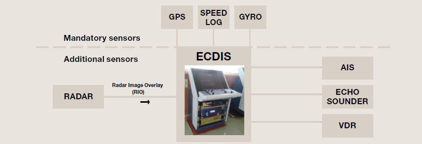
As per IMO performance standards, following minimum interfaces shall be provided to an ECDIS:
a. Ship’s position fixing system
b. Gyro compass
c. Speed and distance measuring device.
However, most modern ECDIS equipment is provided with following additional interfaces:
a. AIS (automatic identification system)
b. RADAR (radar image overlay RIO)
c. VDR (voyage data recorder)
d. Echo Sounder
e. NAVTEX
f. Meteorological instruments such as anemometers (measuring wind speed)
Navigating officers should be aware of which electronic systems are providing sensory inputs to their onboard ECDIS. A failure of sensory input will result in loss of some useful ECDIS information and brief examples of sensory input failure are as mentioned below:
1. Gyro Failure: Course over ground (COG) information (from GPS) will be displayed by the ECDIS
2. GPS Failure: The ECDIS will run in DR mode with position being displayed basis heading and speed log input.
3. Speed Log Failure: ‘Speed Over Ground’ (SOG) instead of Speed Through Water (STW) will be displayed by the ECDIS.
4. AIS Failure: This will result in loss of AIS target overlay.
In case of sensory input failure, the Master shall carry out ‘Risk Assessment’ considering following points;
– Identification of sensory input failure and has the failed sensory input affected the navigation of the ship?
– Does an additional navigational officer need to take over the watch
– Implementation of back-up arrangement such as traditional position fixing method etc.
– Amendment to vessel’s intended passage.
CHART PROCUREMENT
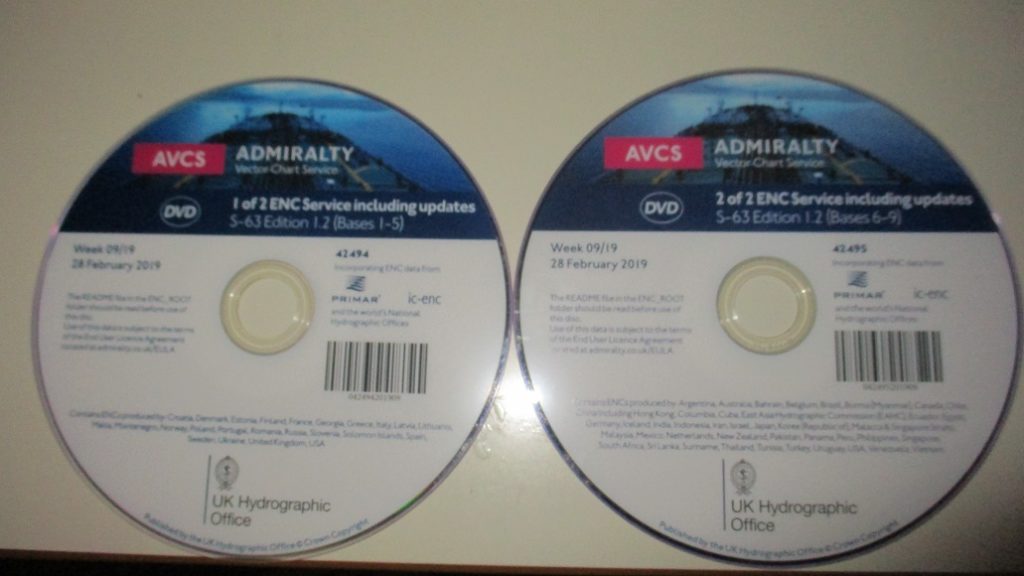
With electronic chart data, all charts are preloaded in the ECDIS equipment using the base CD available onboard, but use can only be made of those for which licenses have been activated. The navigating officer shall consult the digital chart catalogue and required charts for the forthcoming voyages can be activated almost immediately by purchasing the license to activate them.
For areas covered by ENC, only ENC shall be used for the navigation.
CHART CORRECTION
ENCs are updated by weekly ‘Notices to Mariners’ issued by HOs and corrections are received on the vessel either by email or data file (Update CD). The actual updating is either applied to the ECDIS chart database by the user. The ECDIS generates error message when the update is unsuccessful or when a chart is in use and hasn’t been corrected up to date.
After updating ENC charts, modification to the passage plan may be necessary to accommodate new chart features such as reporting schemes, traffic separation schemes, isolated dangers etc. A route check shall be carried out to ensure that any new dangers, which may have been added don’t present a risk to the ship.
Notices to Mariners (NTM): Much of the information in NTM is only for use on paper charts and is not applicable to ENCs or RNCs. However, vessels navigating solely on ECDIS are still required to carry latest NTM (paper copy or digital) to obtain information such as ‘Radio Navigational Warnings’, ‘Amendments to Admiralty Sailing Directions/ Admiralty List of lights and Fog Signals/ Admiralty List of Radio Signals’.
Temporary & Preliminary Notices (T&P): All hydrographic offices do not provide ‘T&P’ Notices in ‘Marine Information Overlay’ (MIO) format. Thus, the navigating officer shall check if applicable T&P notices are shown as ‘MIO’ or ‘Admiralty Information Overlay’ (AIO) format. If not done automatically, T&P data shall be manually inserted into the ECDIS using ‘Manual Update and Mariner’s Notes’ facilities.
When paper charts are used as a back up to Raster Charts, such paper charts must be updated to the latest Notices to Mariners onboard.
Navarea, Navtex and locally broadcasted Warnings: Navigational warnings transmitted by satellite and Navtex receiver are by nature more short term and urgent than T&P notices. Such notices shall be immediately plotted on ENC charts using ‘Marine Information Overlay’ (MIO) facility, where provided.
LIMITATIONS OF ELECTRONIC CHARTS
1. Usage of RNC in ECDIS:
As of now, ENC charts do not cover all sea areas. ECDIS charts provided on board are a combination of ENC and RNC. The Navigating Officers should bear in mind limitations of RNC
2. Information Layer Filtering:
ECDIS may not display some isolated shoal depths when operating in ‘base’ or ‘standard display’ mode. As a result, route planning and monitoring alarms may not always be activated
when approaching such dangers. Caution should be exercised whenever information layers are removed or information level is reduced from an ENC and must be reviewed by the Master. All members of the Bridge Team must be advised whenever such changes are carried out. Master’s standing instructions should include instructions regarding minimum layered information to be displayed. Certain passage plan legs may require addition or removal of some layered information which should be highlighted in the passage plan.
3. Chart Corrections/ Date of Survey:
The Hydrographic offices of various countries process official charts and take on the responsibility of maintaining their accuracy. However, corrections made by these offices might only be available at certain fixed intervals and reliability/ margin of error of a position-fix must be borne in mind.
3. Positions:
Positions are primarily derived from the GPS/DGPS. Therefore any GPS/DGPS alarms must be immediately investigated in order to avoid error in position and the possibility of the vessel running into danger.
4. Scale in Use (Over-scale/ underscale):
There is a risk of running too close to danger with a zoomed-in chart scale. The Navigating Officer should alternatively switch to a smaller chart scale to appraise the situation. All bridge team members shall be aware of the vertical lines indicating over-scale. Using the SCAMIN process, system automatically filters information from ECDIS display. When the display is underscale then certain features are suppressed and the operator runs the risk of not seeing all relevant and possible safety critical information. Autoload and autoscale features are used to minimize the SCAMIN affect. The operator should be careful of the overscale/ underscale effects and select the compilation scale (1:1) for display. The primary ECDIS terminal should, where possible, always be set to the compilation scale (1:1).
5. Radar Overlay:
Positions of other vessels and targets displayed on the ECDIS might be obscured because of improperly tuned radars or improperly set anti-clutter on either the radar or ECDIS. The possibility of offset error is eliminated during the installation phase and later can be recalibrated using the administrative rights in ECDIS.
6. AIS Input:
AIS displays target course and speed over ground as well as heading. However, such target information shall not be used for collision avoidance as the AIS data is based on sensory inputs which may be erratic/ faulty.
7. RADAR Input:
An ECDIS equipped with a radar overlay shall only be used as a situational awareness tool during anti-collision manoeuvres and not for primary anti-collision purposes. The ship’s ARPA radars will be used for this purpose.
8. Depth Units:
Depth unit information is displayed in ECDIS console indicating the depth units in use (meters,feet or fathoms). In case of any changes, the OOW must inform the same to the relieving OOW at the time of handing over the watch.
9. Zones of Confidence (ZOC)
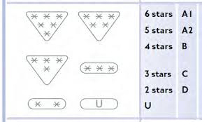
The ‘Zones of Confidence’ (ZOC) indicates that particular ENC meets minimum criteria for position and depth accuracy. It can be looked upon as the survey accuracy. There are six category levels (A1, A2, B, C, D and ‘Unclassified’ wherein A1 is the most accurate survey information). The navigating officer shall be aware of the ZOC for the areas of navigation.
USE OF ECDIS FOR PASSAGE PLANNING
CHECKS PRIOR USING ECDIS FOR APPRAISAL AND PASSAGE PLANNING:
Checklist should be complied with for carrying out passage planning on ECDIS;
Following checks should be carried out by the Navigating Officer while carrying out passage planning on ECDIS:
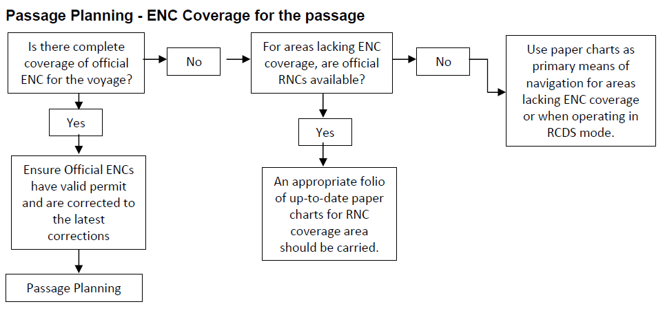
a. Not all sea areas are covered by ENC charts. The electronic chart coverage for the voyage must be adequate and all relevant charts must be fully corrected. For areas covered by ENC, it is mandatory that they be used instead of RNC. If RNCs are to be used, a set of updated paper charts for those areas shall be available onboard and office shall be informed prior commencement of the passage.
b. Check local requirements of coastal states that may require carriage of additional publications or local charts.
c. Check that electronic charts have been updated to the most recent version and chart permit licenses have been bought.
d. The vessel’s controlling operational parameters (maximum draft, air draft, turning data, minimum under keel clearance required, ‘look ahead’ distance etc.) should be entered.
e. The GPS position system should be set to WGS 84 datum.
f. The alarm functions of the ECDIS should be fully operational; they will alert the operator of any danger exposed in good time during the voyage.
g. Carry out ‘Route Check’ to ensure that vessel will not encounter navigational hazards on the planned route.
h. When planning new waypoints and courses, always use the largest scale possible so all features of the chart can be readily identified.
i. Ensure that the plan takes into account sufficient cross-track error (XTE) to accommodate any deviations for collision avoidance or currents.
j. Ensure adequate values are inputted for safety contour and depth alarms.
k. Check that tidal information is up to date and correct.
USE OF ECDIS FOR ROUTE PLANNING
ECDIS provides many benefits for route planning; a few of which are:
1. A quick and easy to select saved routes and prepare new ones.
2. Routes can be easily modified with the use of the planning graphic tool.
3. Measurements and calculations are much easier.
However, planning a safe route requires experience, time and adequate familiarity with the general principles of ECDIS and navigators should be aware of the following:
a. Check Route Function: The navigating officer should make use of the check route function after passage planning to ensure that vessel will not encounter navigational hazards on the planned route. These hazards would be mainly pertaining to grounding dangers, crossing TSS line/ boundary and user defined alarms.
b. On coastal passages, ENCs will be populated with many area related cautions. These may result in numerous warnings being generated during the planning stage leading to missing out of critical item alert. It is important that all warnings/ alarms are carefully checked.
c. Information on an ENC along the route requires to be accessed in full. The procedure for the complete access to information will depend on the make/ model of the ECDIS and is given in the manufacturer’s manual.
d. Navigators should be aware that a geometrically incorrect alarm will be displayed if the distance between two waypoints is very short or if the turn is very sharp. In such a case, the radius and/ or speed should be adjusted to clear the alarm.
e. Proper appraisal of collecting information from the relevant publications needs to be carried out prior plotting route on the ENC.
f. The finally approved route should then be appropriately saved and also copied to the back-up system.
g. Speed Plan: The planned speed for the leg, which will always be at or below the safe speed, after considering the proximity of navigational hazards along the route, the depth of water and the manoeuvring characteristics of the vessel.
h. Turn Information: This can usually be entered by rate of turn or radius. The system will normally calculate one from the other one, and display both parameters using the planned speed for the leg.
i. Markings on the Chart:
The electronic chart should be marked with:
a. Prominent navigation and radar marks
b. Parallel index lines (not from floating objects unless they have been first checked for position)
c. No go areas
d. Landfall targets and lights
e. Clearing lines and bearings, safe distance off
f. Transits, heading marks and leading lines
g. Significant tides or current
h. Safe Speed and necessary speed alterations
i. Call Master Point/ Changes in Machinery Status/ Anchor clearance
j. Minimum under keel clearance
k. Crossing and high density traffic areas
l. Contingency plans/ Abort positions
m. VTS and reporting points
n. Any other user defined notifications as considered necessary
EXECUTION AND MONITORING
a. For change of watch, company checklist to be complied with for carrying out checks on ECDIS.
b. Check that the display has been set-up properly prior to sailing, otherwise important information may not be displayed. There are generally three default settings of the layers of an ENC i.e. Base, Standard and Full. The ENCs should normally be in full access mode. In case the text information clutters the other chart information, the text layer may be disabled.
c. Day/ Night Settings: The display should be set up to meet the appropriate conditions on the bridge. There are three main viewing modes available: daytime, dusk and nighttime.
CAUTION – When using night/ dusk settings, background colours get altered and shoals/ other dangers may not be readily apparent. Until good orientation is achieved, it is advisable to switch to Day settings occasionally.
d. Always use ENC on the best scale possible to avoid crucial information being autofiltered and subsequently not being displayed.
e. When executing a route, progress against the original plan must be constantly monitored.
f. Marking and highlighting of electronic charts should be carried out in a similar way to paper charts. Such marking should identify radar conspicuous targets, no-go areas, parallel index lines, transit marks, clearing bearings, etc.
g. Data input from the gyro compass, speed log, echo sounder and other electronic equipment to the ECDIS should be periodically monitored to ensure accuracy using ‘Sensor Monitor’ window.
h. The look-ahead facility should warn of any hazards ahead off screen but do not rely on it; always use the zoom and scrolling facility to look ahead. Look-ahead range time range for route monitoring is an operator specified parameter. It is important that this time or distance is carefully set to meet the particular circumstances. If set too long it will create numerous alerts that may distract the navigator.
i. Frequent checks should be made of the ECDIS position fixing system (normally GPS) by the use of other means to cross-check and determine vessel’s position. Such checks should include:
a. Parallel indexing and use of clearing bearings
b. Visual cross bearings
c. Use of radar to check the accuracy of the charted position
j. If ARPA overlay is used, targets not acquired by the ARPA will not appear on the ECDIS.
Similarly targets not fitted with AIS will not appear on ECDIS. Therefore, ECDIS should not be used as primary means of collision avoidance.
PRINCIPAL ALARMS AND ALARM SETTING GUIDANCE:
When using ENCs, an alert will be given when charted hazards enter the safety domain, even if the hazard is not visible on the displayed portion of the ENC. The alarms listed below should be kept activated at all times.
Alarms are to be set by the navigating officer at the time of passage planning and once the Master has reviewed the passage/ alarm settings, they should be locked where such a facility is available.
The alert will be an alarm or indication, depending on the circumstances and user settings:
1. Crossing Safety Contours/ Depth:
a. There are generally three contour settings available to the user for highlighting available depth. The contours are differentiated by colours and if a guard zone touches the safety contour it will give an alarm. The contour will be selected only for that value for which a contour exists on the ENC. If any other value is selected, it will then select the next available contour.
i. Safety Contour:
This is a user entered depth that ideally coincides with the contours, giving an adequate safety allowance for the dynamic draft of the vessel.
ii. Deep Contour:
This is user entered depth that will affect the appearance of spot soundings. It uses just two colours. All areas deeper than safety contour are shown in white/ black (depending on day /night settings); all areas shallower than the safety contour are shown in blue.
iii. Shallow Contour:
The navigator emphasizes deep and shallow areas by use of contrast colour using this mode.
b. Safety Depth:
This function is primarily used for the route check and an alarm will be generated upon encountering shallower depth in look-ahead area. The spot soundings below the specified values will appear bold.
Settings found on one vessel:
Shallow Contour: This value should not be less than the gross UKC +max draft.
Safety Contour: This value should not be less than the shallow contour setting value + safety margin (minimum 2 metres)
Safety Depth: This value should not be more than the safety contour setting.
Safety Height: This value should not be less than the air draft of the vessel + 1 metre.
Deep Contour: This value should be more than safety contour and not be less than at least 2 times the draft of the vessel.
2. Area with special conditions:
An alarm or indication, as set by the user, will be given if, within a specified time or distance, own ship would cross the boundary area of a geographic area for which special condition exist such as Traffic Separation Zone, Caution area, anchorage area, Particularly Sensitive Sea Area, Military practice area.
Recommended Settings: To be set at time greater than Position Fixing Interval (PFI) for particular leg of the passage plan.
3. Deviation from route:
An alarm will be given if the specified cross track limit for deviation from the planned route is exceeded.
Recommended Settings: To be determined by the Master after reviewing the passage for proximity of navigational hazards.
4. Positioning system failure:
Navigating officers should be aware of the non-reliability of the GPS input to ECDIS. An error message will be displayed if the GPS signal is lost stating that ‘DR positioning is being used’.
5. Approach to critical point:
An alarm will be given by the ECDIS when the ship reaches a specified time or distance, set by the mariner, in advance of a critical point on the planned route.
Recommended Settings: To be set at time greater than PFI for particular leg of the passage plan.
6. Different geodetic datum:
From data contained within the RNC, ECDIS equipment automatically performs the datum conversion from WGS84 or else it will provide a continuous indication that the referencing cannot be performed. If the datum between RCS and position fixing system is different, it will cause an alarm to be generated to alert the navigating officer.
7. ECDIS failure:
Similar to other electronic navigational equipment, ECDIS can fail, either outright or in a way that can give misleading information. The navigator shall transfer navigation to the back-up system.
8. Approach to mariner entered feature, e.g. area, line:
An indication will be given if, continuing on its present course and speed, over a specified time or distance set by the mariner, own ship will pass closer than a user specified distance from a danger (for example obstruction, wreck, rock or an aid-to-navigation) that is shallower than the mariner’s safety contour or an aid-to-navigation.
Recommended Settings: To be determined by the Master after reviewing subject passage for proximity of hazards.
9. Anti Grounding Cone;
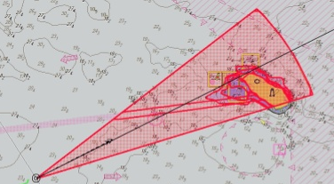
The anti grounding cone (safety frame) is the setting for size of area that will be used by ECDIS for generation of anti grounding alarm, area alert or navigational alarm based on the chart data analysis or the user set safety parameters. The size of anti grounding cone will depend upon ECDIS system in use as well as the size, manoeuvrability and speed of the vessel.
Settings found on one vessel:
Pilotage/ confined waters (vessel dependent):
Ahead – 3 mins, Port – 0.1 nm, Stbd – 0.1 nm.
Coastal waters (vessel dependent):
Ahead – 12 min, Port – 0.1 nm, Stbd – 0.1 nm
Open waters (vessel dependent):
Ahead – 15 min, Port – 0.2 nm, Stbd – 0.2 nm
The navigating officer should never rely solely on automatic alerts as the alert may not give sufficient time or space to avoid the hazard.
The recommended settings mentioned above do not alter the Master’s prerogative to modify or augment anti-grounding cone settings.