Containers
A standard container is basically a rectangular box with 5 sides closed and the sixth being the door. A box can be constructed in many ways, two most commonly used methods are:
(a) Construction using same material throughout &
(b) Using a frame and attaching varying materials to the frame.
The example of the former is the cartons used for TVs etc. Advantages of such a construction is that same material is used throughout with doubling of the material at the bottom and top, this saves cost and time in construction, but such boxes can only be used for small quantities and lightweights.
An example of the frame method of construction is the ordinary cupboard. Here the frame bears the weight and hence each shelf can then be constructed of varying strength depending on the use. The sides can also be varied and doors, which are constantly in use, can be made stronger It is costlier but saving on material and better strength makes up for the cost. It also can be used again and again.
In its simplest form construction of a ship is also frame method of construction.
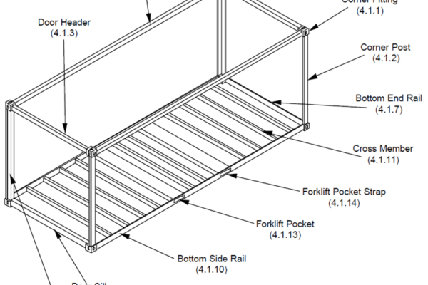
Primary Structural Components for a Typical 20′ ISO Shipping Container.
Note: On some ISO shelters, some of the primary structural components may be concealed within the wall, roof, and floor panels. The areas where the adjacent panels join will be thoroughly inspected. This inspection will meet the criteria for the Wall Beams and the Roof Beams.
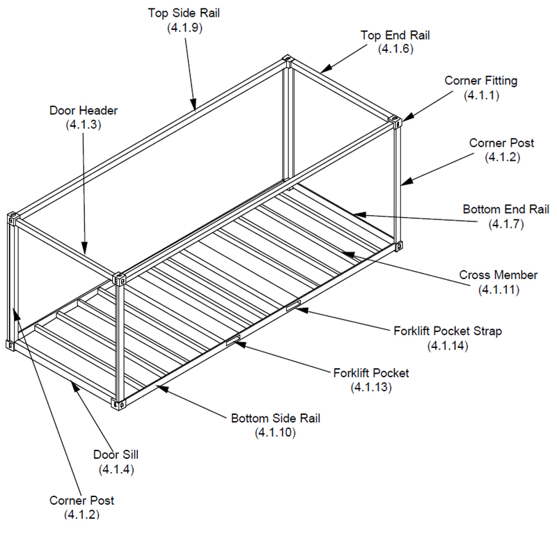
Corner Fitting. Internationally standard fitting (casting) located at the eight corners of the container structure to provide means of handling, stacking and securing containers. Specifications are defined in ISO 1161.
Corner Post. Vertical structural member located at the four corners of the container and to which the corner fittings are joined.
Door Header. Lateral structural member situated over the door opening and joined to the corner fittings in the door end frame.
Door Sill. Lateral structural member at the bottom of the door opening and joined to the corner fittings in the door end frame.
Rear End Frame. The structural assembly at the rear (door end) of the container consisting of the door sill and header joined at the rear corner fittings to the rear corner posts to form the door opening.
Top End Rail. Lateral structural member situated at the top edge of the front end (opposite the door end) of the container and joined to the corner fittings.
Bottom End Rail. Lateral structural member situated at the bottom edge of the front end (opposite the door end) of the container and joined to the corner fittings.
Front End Frame. The structural assembly at the front end (opposite the door end) of the container consisting of top and bottom end rails joined at the front corner fittings to the front corner posts.
Top Side Rail. Longitudinal structural member situated at the top edge of each side of the container and joined to the corner fittings of the end frames.
Bottom Side Rail. Longitudinal structural member situated at the bottom edge of each side of the container and joined to the corner fittings to form a part of the understructure.
Cross Member. Lateral structural member attached to the bottom side rails that support the flooring.
Understructure. An assembly consisting of bottom side and end rails, door sill (when applicable), cross members and forklift pockets.
Forklift Pocket. Reinforced tunnel (installed in pairs) situated transversely across the understructure and providing openings in the bottom side rails at ISO prescribed positions to enable either empty capacity or empty and loaded capacity container handling by forklift equipment.
Forklift Pocket Strap. The plate welded to the bottom of each forklift pocket opening or part of bottom side rail. The forklift pocket strap is a component of the forklift pocket.
Gooseneck Tunnel. Recessed area in the forward portion of the understructure to accommodate transport by a gooseneck chassis. This feature is more common in forty foot and longer containers.
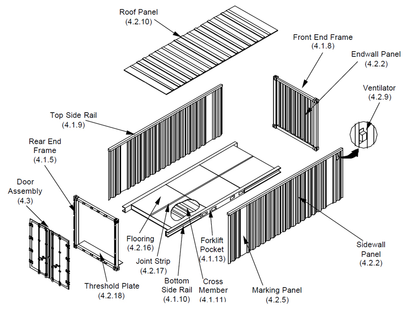
Exploded axonometric view of a typical 20′ ISO Shipping Container.
Fiberglas Reinforced Plywood (FRP). A material constructed of laminates of fibreglass, polyester resins, and plywood, also known as sandwich panel.
Wall Panel. Corrugated or flat sheet steel, a riveted or bonded aluminium sheet and wall post assembly, FRP, foam and beam, aluminium, or honeycomb material that forms the side wall or end wall.
Wall Post. Interior or exterior intermediate vertical component to which sheet aluminium or steel is riveted or welded to form a wall panel.
Wall Beam. Encapsulated vertical component to which sheet aluminium or steel is bonded to form a wall panel. This is found in foam and beam panels.
Marking Panel. A side wall panel of a corrugated steel configured with a flat portion used for the display of markings and placards. (4.2A)
Lining. Plywood or other like material attached to the interior side and end wall to protect the walls and/or cargo and facilitate loading operations.
Lining Shield. A strip of thin metal installed at the bottom of the interior walls to protect the lower portion of the lining from damage by materials handling equipment during loading or unloading operations.
Kick Plate. A common name for a lining shield installed on the lower portion of the interior front end wall.
Ventilator. Two or more devices permanently attached to the side or end wall panel that provides openings for the exchange of air (but not water) between the outside and the container interior.
Roof Panel. Corrugated or flat sheet steel, sheet aluminium, FRP, or foam and beam and aluminium honeycomb panel that forms the top closure of the container.
Roof Bow. Lateral non-structural member attached to the top side rails and supporting the underside of the roof panel. Roof bows used with removable cover (tarp) assembly are unattached. Not all container designs require roof bows.
Roof Beam. Encapsulated horizontal component to which sheet aluminium or steel is bonded to form a roof panel.
Roof Reinforcement Plate. An additional metal plate on the interior or exterior of the roof panel adjacent to the top corner fittings that provides protection of the roof panel or top rail components from misaligned handling equipment.
Tarp. Jargon for “tarpaulin” which is a waterproof and flexible fabric used for covering the top of an open-top container. This covering is referred to as a “Tilt” in some countries.
TIR Cable. Plastic sheathed wire rope that is designed in accordance with TIR customs convention and is threaded through the welded loops on the sides, end panels and door panels of an open-top container to secure the tarp.
Flooring. Material that is supported by the cross members and bottom rails to form a load bearing surface for the cargo. The flooring is usually constructed of laminated wood planks, plywood sheets, or other composition material and is screwed or bolted to the cross members. Some containers have welded steel or aluminium flooring, sandwich panels or a combination of metal and wood.
Joint Strip. A formed steel or aluminium strip (usually hat-shaped section) installed between joints of the plywood sheet flooring or joints of the plywood sheet lining to help integrate and support the edges of the plywood.
Threshold plate. Plate forward of the door sill to protect the entrance area of the container floor. This plate is commonly referred to as a crash plate.
Steps. Folding steps are found on some ISO Shelters and are used to gain access to the roof. They must be folded up prior to transporting shelter.
Sandwich Panel. A type of fixed or removable panel construction used in ISO Shelters consisting of a thin inner and outer sheet aluminium skin, bonded or fastened to a core constructed of either honeycomb or structural foam and aluminium beams.
Striker Plate. An additional metal plate on the exterior of the roof panel adjacent to the top corner fittings that provides protection to the roof panel or top rail components from misaligned handling equipment.
Sling Pad. An additional metal plate on the exterior of the roof panel located in the center of the roof panel that provides protection to the panel from lowered handling equipment.
Position and securing of containers on board
General on-board stowage
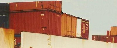
On most ships which are specially designed for container traffic, the containers are carried lengthwise:
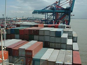
This stowage method is sensible with regard to the interplay of stresses in rough seas and the loading capacity of containers. Stresses in rough seas are greater athwartships than fore and aft and the loading capacity of container side walls is designed to be higher than that of the end walls.
However, on many ships the containers are stowed in athwartships bays or are transported athwartships for other reasons. This must be taken into consideration when packing containers and securing cargo.
This stowage method is not sensible with regard to the stresses in rough seas and the loading capacity of containers. Stresses in rough seas are greater athwartships than fore and aft but the loading capacity of container end walls is lower than that of the side walls.
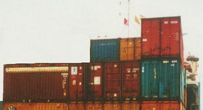
Even unusual stowage methods like this, where some of the containers are stowed athwartships and others fore and aft, are used, but they require greater effort during packing and securing operations.
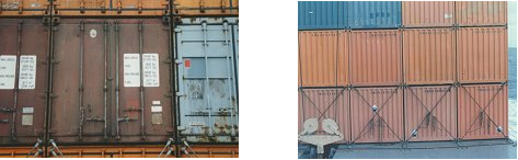
The above two pictures show how important it is to find out about the various carriers and their way of transporting containers, either in order to rule out certain modes of transport or to be able to match cargo securing to mode of transport. If the method of transporting a container is not known, then packing and securing have to be geared to the greater stresses.
General securing information
When securing containers on board, the stresses resulting from the ship’s movements and wind pressure must be taken into account. Forces resulting from breaking-wave impact can only be taken into account to a certain degree. All the containers on board must be secured against slippage and toppling; with care being taken to ensure that the load-carrying parts of the containers are not loaded beyond admissible levels.
Except in the case of individually carried containers, securing is effected by stacking the containers in vertical guide rails or by stowing them in stacks or blocks, the containers being connected together and fixed to parts of the vessel.
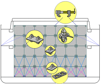
Securing in vessel holds by cell guides alone
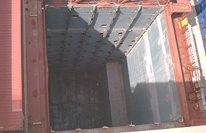
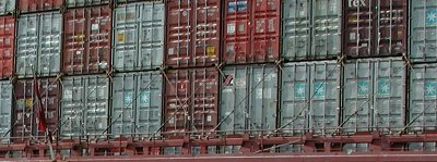
Virtually all all-container ships are provided with cell guides with vertical guide rails as securing means for hold cargoes. The greatest stress the containers are exposed to stems from stack pressure. Since the containers are not connected together vertically, lateral stress is transmitted by each individual container to the cell guides when positioned in such cell guides, individual containers are not usually able to shift. If the corner posts of one of the containers at the bottom of a stack collapse under excessive pressure, containers stowed above it generally suffer only slight damage. The risk of damage to containers in adjacent stacks is kept within tight limits.
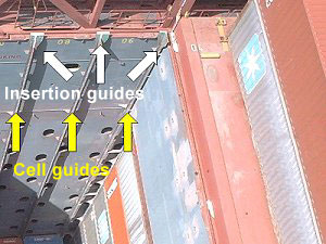
The containers are guided by these rails of the cell guides during loading and unloading. The photo shows clearly that the upper ends of the guide rails each take the form of insertion guides.
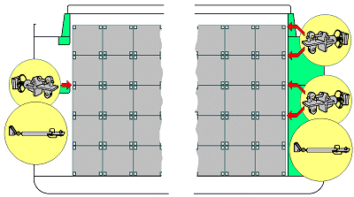
Securing in vessel holds by cell guides and pins
Feeder ships, multipurpose freighters and container ships in certain regions have to be particularly flexibly equipped, in order to be able to carry containers of different dimensions. To this end, convertible stowage frames have been developed, in which 20′, 24½’, 30′, 40′, 45′, 48′ and 49′ containers may be stowed securely without appreciable delay.
Most of these frames are produced as panels which are brought into the required positions by cranes. At the bottom they mainly have fixed cones, which engage in pockets welded into the tank top area. At the sides, the frames are secured by pins, which engage in bushes which are let into the wing bulkheads. Such frames are often man-accessible, so that the containers can be locked in place by means of pins.
If it is necessary to be able to carry containers 2,500 mm wide, the frames are arranged on the basis of this dimension. To secure standard containers of normal width, closure rails are then fitted on both sides of the guide rails by means of screw connections. If necessary, these adapters may be removed.
Removable container guides have also been developed and constructed for multipurpose freighters, reefer vessels and the like. Such guides allow containers to be carried in regular or insulated holds without any risk of damage to the holds themselves. If other cargoes are carried, the stowage guides may be removed using ship’s or shore-based loading or lifting gear and deposited in special holders on deck.
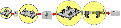
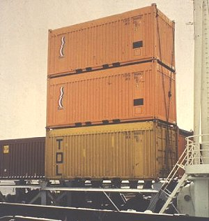
Securing in vessel holds by conventional securing and stacked stowage
On older, conventional general cargo vessels and multipurpose freighters, stacked stowage methods are used in the hold, combined with various securing methods:
The lower containers stand on foundations capable of withstanding the stack pressures which arise. Dovetail foundations, into which sliding cones fit, are provided to prevent slippage. The containers are connected together by single or double stacking cones or twist locks. The entire stack or container block is lashed using lashing wires or rods and turnbuckles. This system entails a lot of lashing work and material and, moreover, is less secure than securing in cell guides.
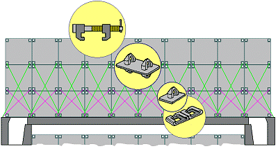
Securing in vessel holds by block stowage and stabilization
This securing method is found less and less frequently, but it is still found on some con/bulkers and other multipurpose freighters. Containers are interconnected horizontally and vertically using single, double and possibly quadruple stacking cones. The top tiers are connected by means of bridge fittings.
To the sides, the containers are supported at their corner castings with “pressure/tension elements”.
This type of container securing has two marked disadvantages:
If an individual container breaks, it is not just one container stack which is affected, but the whole container block.
Due to dimensional tolerances and wear and tear to the stacking cones, the entire block can move constantly in rough seas. This causes the intermediate stacking cones to break and an entire block may collapse.
Securing on deck using container guides
On some ships, containers are also secured on deck in cell guides or lashing frames. Some years ago, Atlantic Container Lines used only cell guides on deck. Certain ships belonging to Polish Ocean Lines had combined systems. In other ships, cell guides can be pushed hydraulically over the hatch cover as soon as loading below deck is completed and the hatches have been covered up.
Securing on deck using block stowage securing
This method was used a lot in the early days of container ships, but has been used less and less in recent years for economic reasons.
The containers in the bottom layer are positioned in socket elements or on fixed cones. Double stacking cones are used between the layers and the corner castings of adjoining containers are connected at the top by bridge fittings. The containers are held together over the entire width of the ship or hatch cover by cross lashings. A distinct disadvantage of this method is reduced flexibility when loading and unloading, since adjoining containers have always to be moved as well if access to a particular container is required.
Numerous variants, not listed any greater detail here, are available for attaching the lashings. Sometimes the lashings from different stacks cross one another.
Securing on deck using stacked stowage securing
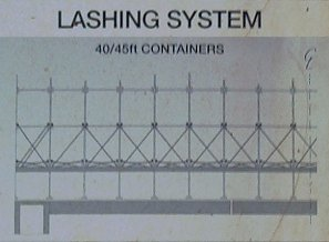
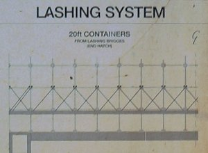
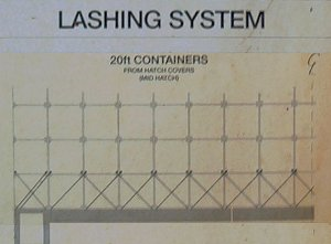
This securing method is the one used most frequently. Cargo handling flexibility is its key advantage. The containers are stacked one on top of the other, connected with twist and lashed vertically. No stack is connected with any other stack. The container lashings do not cross over the lashings from other stacks, except for the “wind lashings” on the outer sides of the ship.
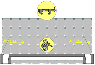
Obviously, a container stack of this kind can topple if it is not adequately secured.
An absence of special equipment for securing containers and unfavourable stowage spaces increase the risk for container cargoes. “Sloppy” carriers should be avoided wherever possible. This applies quite generally, not only to the operators of aging ships. Timely information about as many as of the circumstances and procedures encountered during carriage as possible can be extremely useful.
Stresses on containers
Containers are subject to various stresses and failure of the container to withstand these stresses will result in damage to container. The stresses can be broadly grouped into:
- transport mode
- handling mode
- environment
- cargo and
- ‘G’ force.
Transport mode
The containers are transported both at sea and on land; each mode creates its own stresses.
Sea transport
In sea transport stage the container suffers from:
- The racking stresses. This can cause severe damage to end frames, doors and panels. This is prevented by cross-lashings.
- Damage caused when a container comes loose. Besides the damage to itself a single container coming loose from its lashings can cause very severe damage to the ship and sometimes the environment.
- Damage is also caused by cargo inside the container becoming loose due to vessel rolling and pitching.
- Damage caused during transfer of container to and from the ship. This is generally caused either by wrong use of spreaders, which result in damage to the roof.
- Wrong use of slings cause damage to side rails and ends frames.
- Loading in cell guides causes abrasion damage and any obstruction in cell guide can cause panels to rip-off.
- Wrong handling cause damage to top and bottom.
Handling mode
Containers are handled by various methods, chief of these are gantry, forklifts and straddle carriers. These are used for lifting and short movements of container. Top lifting can cause roof damage while bottom lifts by forklifts can cause bottom rail damage. Sudden stoppage of forklift and straddle carriers causes the container to swing and this can cause deformation in the frame; it can also cause cargo inside to shift causing panel damage.
Environment
Environment damage to the container is caused due to continuous exposure of the container and the sea waves striking the containers on deck. Temperature variations also cause damage; specially freezing temperatures coupled with water, due to expansion of water freezing to ice. This has severe effects on doors and hinges. Tropical high temperatures also cause damage specially loosening of joints and deformation of parts.
Cargo
Cargo damage can be due to:
- Improper weight distribution and
- Improper dunnage and securing.
The weight distribution should be even with the centre of gravity of the container around its geometrical centre. Uneven distribution may cause damage to the side rails during lifting or may even break the floor. Improper securing and dunnaging can cause the cargo to shift and cause side and end panel damage. It should be borne in mind that almost all containers are loaded or “stuffed” by the exporter of the cargo who is unaware of the importance of proper securing or even distribution of weight and ignorant of its consequences.
‘G’ force
Containers, when they are being lowered, are subject to acceleration due to gravity. When a container is landed, this force is transmitted to the corner post of the container below and the container itself. This force can increase the weight of the container to nearly double. Stack weights for containers are calculated allowing for 1.8 g. Vibrations can also cause damage to containers, especially if the container vibrates at its natural frequency.
Container construction should take into account all these to ensure that containers can withstand these forces, otherwise repairs to containers will result in disproportionate expenditure.
Container Examinations
Every container must have a Container Safety Certificate (CSC) issued by the manufacturer and this must be renewed every 30 months after inspection by a competent inspector. An Approved Continuous Examination Programme (ACEP) can be agreed as substitute for this procedure and the ACEP number is stamped on the CSC plate. Most company’s containers are inspected under an ACEP scheme.
Container Damage
Common types of container damage are listed below.
Racking: Is the twisting of the structural shell of the container due to static or dynamic forces and is commonly associated with movements in a seaway. The standard ISO container racking limit is nominally 15 tonnes. To counter these forces, diagonal lashings may be applied in accordance with the vessel’s lashing system. In high stacks, the lower container is subject to the greatest racking forces and the lashing systems must be designed to take this into account.
Toppling: Can occur when containers are subjected to extreme rolling motions aboard ship or standing in a stack, exposed to high winds. Counter measures are twistlocks and lashings.
Container collapse (corner-post compression): Results from exceeding allowable loads on the container corner posts and can be avoided by staying within weights limits of the container. Where lashings are applied aboard ship, avoid over tensioning of lashings.
Local structural failure: Is the separation of structural components of a container such as side-wall separation from top and bottom rails and separation of the corner castings from the side rails.
Holes in containers: are the most common kinds of damage. Roof damage is often caused by lifting spreaders indenting the roof when locating corner castings and twistlocks and lashing gear being thrown down on top. Holes in container walls can be caused by fork-lift trucks, collision with other containers or lifting devices. Holes in containers can be easily detected by interior inspection with the doors closed and noting any light entering the container. This can also reveal faulty door seal gaskets and is extremely important check to be made.
Interior Contamination: Container floors become seriously contaminated by cargoes such as wet hides which can cause tainting to future cargoes. Interior paintwork can also be stripped by cargoes such as naphthalene and cloves.
Container Repairs
P&O Nedlloyd seeks to maintain the containers in a safe and acceptable condition both operationally and visually, whilst avoiding overspending on structural and cosmetic repairs such as small dents and scuffing of paintwork.
Container Cleanliness
P&O Nedlloyd set cleanliness criteria for cleaning containers. This includes appropriate detergents to be used in order that taint to cargoes is not caused by cleaning agents.
Containerization can lead to cost savings through improved efficiency, reduced labor requirements, and minimized pilferage and damage.