These are oil tankers specially meant for storage of oil offshore. Hence, they are converted sailing oil tankers. Conversions are customized to meet the requirements of the location where the FSO needs to be placed. Thus each FSO has certain unique features, which may not be found on other FSOs.
A FSO should not be confused with a FPSO – “Floating Production Storage and Offtake” tanker.
The FPSO has an additional function of production of oil besides functioning as an FSO. FPSO is not within the scope of this literature. Hence, we shall study FSO furthermore.
The need for FSOs was felt by the oil industry when oil was discovered and drilled from under the sea-bed in locations which were either too far from land to have underwater pipelines or in regions which had the oil reserves underwater but did not have the resources to have pipelines to the shore for transporting the oil. FSOs are stationed mainly in Asia, Africa, South America and Australia.
Location
FSOs are generally located within 1-2miles from the drilling/production platforms. Areas in the vicinity are generally charted as “Restricted Areas”. Mariners should give a wide berth to these areas.
Mooring: FSOs are generally moored to the seabed as described below:
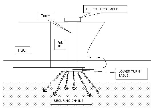
SPT: This abbreviation is for “Single Point Turret” mooring. A turret is built in the fore part of the FSO passing through the forepeak tank. This turret extends from the deck to the ship’s bottom forward.
The bottom end has a turntable, which has six to eight mooring chains located equidistant from each other around the circumference of the turntable. These mooring chains are anchored to the seabed. The vessel pivots around the turret. The turret also houses the loading pipeline, which runs from the oil production platform to the FSO.
Typical SPT bow mooring arrangement is depicted hereunder.
FSOs are generally located within 1-2miles from the drilling/production platforms. Areas in the vicinity are generally charted as “Restricted Areas”. Mariners should give a wide berth to these areas.
Mooring
FSOs are generally moored to the seabed by SPT, SPM or MAMS.
1. SPT: This abbreviation is for “Single Point Turret” mooring. A turret is built in the fore part of the FSO passing through the forepeak tank. This turret extends from the deck to the ship’s bottom forward.
The bottom end has a turntable, which has six to eight mooring chains located equidistant from each other around the circumference of the turntable. These mooring chains are anchored to the seabed. The vessel pivots around the turret. The turret also houses the loading pipeline, which runs from the oil production platform to the FSO.
Typical SPT bow mooring arrangement is depicted hereunder.
2. SPM: This is an abbreviation for Single Point Mooring. There are two main types of SPM’s viz.; CALM and SALM.
- CALM. “Caternary Anchor Leg Mooring”. This system has a large buoy moored to the seabed by at least four anchor chains, which lie at a distance of up to 400 meters from the buoy. FSOs are generally moored to CALM buoys by two mooring chains.
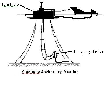
A typical CALM buoy and FSO arrangement is illustrated above
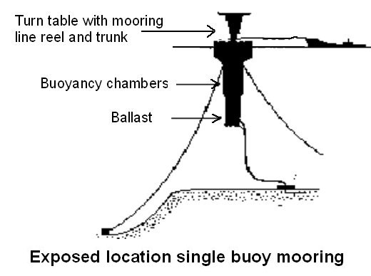
Variants to CALM are ELSBM – “Exposed Location Single Buoy Mooring” and Spar mooring.
ELSBM’s are located in areas where bad weather is commonly encountered. The anchors of ELSBM’s may lie up to half a mile from the buoy. ELSBM’s are surmounted by a helicopter platform, has reels for lifting hawsers and hoses clear of the water and is fitted with emergency accommodation.
- Typical ELSBM is illustrated below.
Spar moorings are similar to ELSBM’s but the floating structure is larger and includes oil storage facilities so that in adverse weather, production is not stopped. Spar moorings are permanently manned.
An illustration of a Spar mooring buoy is as shown below.
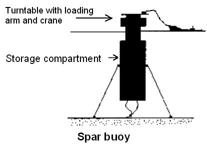
FSOs moored to ELSBM’s and Spar moorings are generally fitted with a quick disconnect coupling in the fore end to disconnect the FSO from the buoy rapidly in case of adverse conditions.
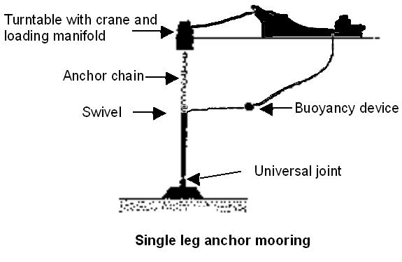
- SALM. “Single Anchor Leg Mooring”. This consists of rigid framing or tubing with a buoyancy device at its upper end. It is secured to the seabed by a large concrete or steel base. This type of mooring is suitable for loading from deep-water sub-sea wellheads. FSOs moored to SALM pull the buoy and at times this causes the frame of the buoy to tilt towards the vessel and the buoy to dip into the water at the vessel’s end.
A typical SALM buoy arrangement is as shown.
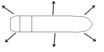
3. MAMS: This abbreviation is for “Multiple Anchor Mooring System”. Six to eight anchors are laid out from all around the FSO in different directions at equal angles of the compass. This mooring system is found on locations where the water depth available for mooring the FSO is less. FSOs moored in this manner are incapable of swinging to the wind or tide while in operation.
A typical mooring arrangement is illustrated hereunder.
Loading
Loading of FSO is carried out by means of dedicated loading lines. These lines generally emerge from the bow of the FSO and lead to a set of two to four centre tanks. Loading rates vary. The factors governing loading rate are past life of the wellheads, future exploration and drilling plans, size and condition of the sub-sea piping and commercial requirements like production targets, international oil prices and the demand and supply of the particular grade of crude oil in the world oil markets.
Loading is a continuous operation on FSOs as long as production continues and weather permits.
This normally continues uninterrupted for many years.
In adverse weather conditions, the FSO may be required to be cast off from the buoy moorings. Under these circumstances, loading of FSO would be suspended. If crude oil being produced has a high pour point, then the oil content in the subsea pipeline may freeze and render the pipeline unusable for future use. This is prevented by injecting antifreeze chemicals into the subsea pipeline prior to unmooring of the FSO.
Storage
Loaded oil is subject to decanting and internal shifting of oil from the tanks being loaded to other tanks. Here, one must bear in mind that there are two main processes involved in drilling/production of oil. Viz.: Water injection and Gas injection.
If the crude oil were produced by means of water injection, the oil would contain some suspended water. This water in the crude oil needs to be decanted to reduce the BSW content of the oil. The water content in the loaded tank of the FSO is allowed to settle down. Further separation of oil and water in these tanks is achieved by heating the loaded tank by steam coils.
The water column from the loaded tank is then transferred to the primary slop tank for further settling down. It is then further heated and transferred to the secondary slop tank. From the secondary slop tank, it may pass through an oily water separator and then it is pumped overboard in compliance with international oil pollution regulations as well as local regulations.
The oil content of the loaded tank is transferred to other holding tanks. These are normally the wing tanks and the centre tanks not provided with the loading connection. The holding tanks hold the oil, which is ready for discharge. Oil samples from holding tanks are frequently drawn and analyzed to ensure that the oil stored meets the laid down specifications.
If the oil is produced by Gas injection method, the oil is more volatile. The oil thus emanates a lot of gases as it settles down in the loading tanks of FSOs. This gas needs to be vented regularly to prevent overpressure of FSO tanks. Venting of gases is carried out in compliance with safe tanker practices.
The oil from the loaded tanks is transferred on a regular basis to the holding tanks. The procedure of internal oil transfer and storage of oil for both types i.e. Water injected and Gas injected oil remains identical.
Off-take or Discharge
Discharge operations are carried out as required. Operational factors governing discharge plans and frequency of discharge operations would be production rate, storage capacity of the FSO, decanting/venting capacity of the FSO, ullage space available in the holding tank of the FSO, availability of suitable daughter tankers for offtake and availability of necessary manpower (Pilots, mooring teams and other officials) and tugs or supply vessels.
There are special pilots who specialize in mooring of daughter tankers to FSOs. They are frequently called in especially from other countries and locations exclusively for FSO offtake operations.
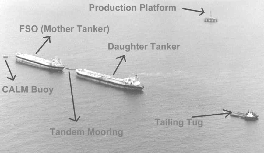
Off-take operations are normally carried out by means of “Tandem Mooring” of daughter tanker to FSO. FSOs have an export line with one or two export manifolds located on the poop deck of the FSO. These manifolds have floating hoses permanently rigged to them.
Permanent tandem mooring arrangement is also located on the poop deck of the FSO. This mooring arrangement is secured to the bow of the daughter tanker in compliance with OCIMF mooring requirements.
After the daughter tanker mooring is secured, the support vessel in the vicinity transfers the floating end of the hose from the stern of the FSO to the port manifold of the daughter tanker. Once hose connections are made on the daughter tanker and both vessels – viz. FSO and daughter tanker are ready for cargo transfer operations, cargo transfer is carried out.
An accurate count of the oil quantity is maintained by passing the cargo through a ‘Metering Skid’ on the FSO before the cargo flows out of the export manifold of the FSO.
The metering skid is a highly sophisticated form of the basic flow meter. It is computer controlled and tamper proof. Thus it provides a highly accurate account of the oil quantity transferred. The cargo quantities obtained from the metering skid are used to prepare Bills of Lading upon completion of transfer operations.
For operating the metering skid correctly, a minimum continuous flow of oil is required. This is achieved by avoiding sole direct stripping of FSOs tanks into the discharge line.
Before the oil passes through the cargo manifold of the FSO, a small quantity is dripped continuously into an automatic sampler. Chemists and Laboratory technicians onboard continuously analyze these samples in the specially equipped laboratory. At the end of the cargo transfer operations, they prepare a complete analysis report of the cargo. The ‘Certificate of Quality” is derived from this report.
The tension on the mooring arrangement between the FSO and the daughter tanker is monitored continuously by means of a “‘Load Cell”.
The load cell gives continuous readout as well as a graphical display of the tension on the mooring hawser. The display and graph is located in the CCR of the FSO.
The tailing tug – which is normally kept secured to the stern of the daughter tanker, is manoeuvred as required to maintain the bow of the daughter tanker at a safe distance and at the same time avoiding excessive tension on the mooring arrangement.
On FSOs moored to SPMs, a similar arrangement is also fitted on the bow of the FSO to monitor hawser loads forward.
Upon completion of cargo transfer, the export hose may need to be flushed with water. This operation is generally required when handling cargoes with high pour point to prevent freezing of cargo in the floating hose. This is achieved either by a water flush from the daughter tanker into the FSO or Vice-versa. This operation is normally planned in advance – prior to the daughter tanker arriving in the field. Normally a slop tank is kept on FSO or on the daughter tanker as appropriate exclusively for this purpose.
The hose is then disconnected from the daughter tanker and cleared from the daughter tanker’s shipside. Once an agreement is reached between the FSO master and the daughter vessel’s master, the unmooring operation of the daughter vessel is carried out.
A typical off take operation showing the various entities involved is depicted hereunder.
Other Associated Operations
Other associated operations onboard FSOs besides the primary FSO operations described above are broadly listed as follows:
1. Helicopter operations.
2. Hotelier service.
3. Power generation and distribution.
4. Bunkering and fresh water storage and supply.
Helicopter Operations
FSOs are generally equipped with a helideck specially constructed in the aft of the vessel. Personnel travelling between the oil field and the shore base normally travel by helicopter. The FSO thus acts as an “Offshore Oilfield Airport”. Personnel travel between the FSO and the various oilrigs by support vessel. Transfer of personnel between FSO and support vessel is carried out by using a “Personnel Transfer Basket” rigged with a crane. FSOs generally have a crane located close inboard of the shipside with a long boom for this purpose. Helicopter operations onboard FSOs are handled by ‘HLO’ – Helicopter Landing Officer who works under the FSO master’s supervision.
Hotelier service
FSOs generally have a very large accommodation area supplemented by large capacities of LSA. They provide off work hotel facilities to personnel working in the various locations in the oilfield.
Power generation and distribution
Gas produced from the oilfield is piped to FSOs for running the turbines. These turbines generate electrical power. The electrical power is transmitted from the FSO to other installations in the oilfield by specially laid power cables.
Bunker and Fresh water storage and supply
FSOs have specially dedicated tanks for these purposes. Fresh Water generators of very large capacity are fitted on FSOs to meet the fresh water requirements of the entire oilfield. Bunkers for all vessels and installations operating in the oilfield are generally stored on FSO bunker tanks. Support vessels come alongside the FSO and receive bunkers and fresh water for their own needs as well as the needs of the other fixed installations in the field. Bunker supplies to FSOs are also usually carried out via Tandem mooring of Bunker vessel to FSO. The export manifold located aft is used for bunkering FSOs. Thus FSOs sometimes have the unique feature of having an interconnection between cargo and bunker lines. This interconnection is used only during bunkering of FSO and is generally blanked off at all other times.
MARPOL Requirements
Regulation 21 of Annex I of MARPOL 73/78 deals with FSOs.
As per this rule, they shall comply with regulation 16 (Oil discharge monitoring and control system and oil filtering equipment) and regulation 17 (Tanks for oil residues (Sludge)).
They shall keep a record of all operations involving oil or oily mixture discharges.
They shall comply with regulation 11 with regard to discharge into sea of oil or oily mixtures.
Thus FSOs are basically large oil tankers, which are involved, in a complex array of operations. It should be noted that besides the additional fittings as required for the above mentioned operations, there are some equipment normally found on sailing oil tankers which may not be found on FSOs. Examples of these would be Main engines, propeller, rudder and anchors. On some occasions, during conversion from sailing oil tanker to FSO, the bridge of the vessel is modified and converted to an auditorium solely for recreational purposes.
All normal safe tanker practices and procedures as laid down in the various IMO, ICS, OCIMF, ISF publications and tanker industry requirements are applicable on FSOs. Additionally FSO operators lay down FSO specific operational procedures and guidelines. These are strictly adhered to and complied with at all times on all FSOs…