Piping system
The bilge system is used to remove small quantities of fluid that have leaked or condensed into a dry space. The system serves the machinery spaces, cargo holds, cofferdams, voids, stores, tunnels and pump rooms. Each space has its own piping but the pump is likely to be shared.
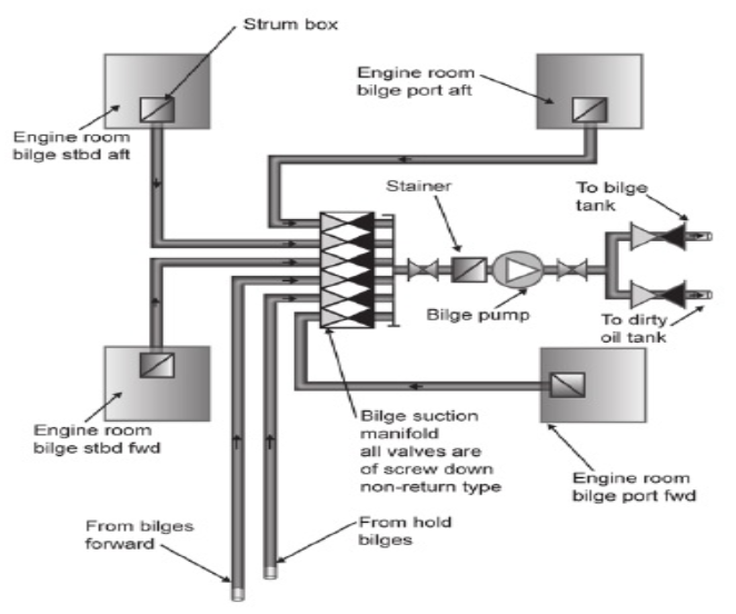
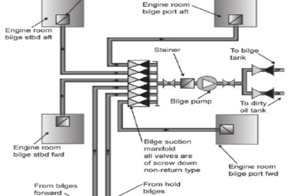
- The engine room bilges, usually located at the four corners of the engine room.
- The engine room bilges may have oily water.
- The oily bilges should never be pump directly overboard and is first transferred to a decanting tank.
- Here they are allowed to settle and separation of oil takes place by gravity.
- The tank is also provided with steam heating as heating assists separation.
- Oil is skimmed from the top or drained to the sludge tank.
- The water is drained to the bilge holding tank.
- From here, the bilge water is pumped overboard through the oily water separator, and the oil concentration of the affluent, the discharge water does not exceed 15 ppm.
- The separated oil from the oily water separator discharges into a sludge tank.
- Sludge tanks are storage tank for oily water with a high percentage of oil and little water.
- The sludge pumps transfer the oily sludge to the incinerator waste oil tanks after which they are incinerated in the incinerator.
Features of bilge system
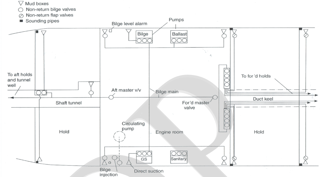
- A vertical drop pipe would lead down to the bilge. Each bilge suction branch is controlled by screw down non return (SDNR) valve
- All bilge pipes shall be provided with mud boxes. Suction pipe ends should be enclosed in easily removable strum boxes.
- Sounding pipes where provided are to be straight as possible, easily accessible provided with closing plugs. Additionally, machinery space pipes shall have self-closing cocks.
- The capacity of a bilge system is defined by the diameter of the bilge main and pump capacity for the volume of the enclosed space.
- Cargo ships are required to have two bilge pumps with non-return valves fitted to prevent back-flow or cross-flow.
- The requirements for bilge systems on ships carrying dangerous goods are basically the same as for cargo ships. However, systems drawing fluids from gas-dangerous spaces are kept segregated with their own pumps and pipes, where appropriate, from systems serving gas- safe spaces.
- The pumping system in a passenger ship must be able to drain water from any dry space when one or more of the ship’s other compartments are flooded. However, the system is not required to empty the flooded space.
- A flooded passenger ship is required to have at least one bilge pump, with its own power supply, available for pumping at all times. Bilge suctions must have remotely operated suction valves. The minimum number of pumps required is three or four, depending on the ship’s design.
Emergency Bilge suction
The emergency bilge suction or bilge injection valve is used to prevent flooding of the ship. In accordance with solas requirements, bilge suction valve is a normally closed non-return valve with positive means of closing and the emergency bilge suction piping is located inboard of a shell valve.
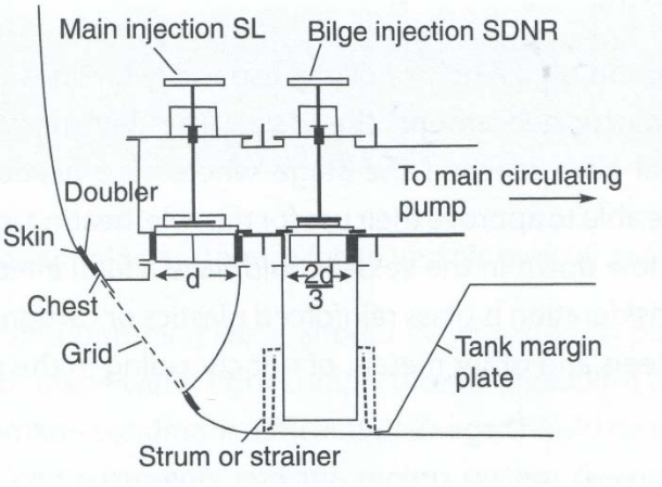
It is a direct suction from the machinery space bilge which is connected to the largest capacity pump or pumps.
There is a strainer attached to the bilge injection valve.
SOLAS requires that the diameter of this injection valve is at least 2/3 times the main suction.
The spindles of the sea inlet and injection valves shall extend well above the engine-room platform.
The ballast system
- The ballast system is arranged to ensure that water can be drawn from any tank or the sea and discharged to any other tank or the sea as required to trim the vessel.
- Combined or separate mains for suction and discharge may be provided.
- Where a tank or cargo space can be used for ballast or dry cargo then either a ballast or bilge connection will be required.
- The system must therefore be arranged so that only the appropriate pipeline is in service; the other must be securely blanked or closed off.
- Where tanks are arranged for either oil or ballast a change-over blanks must be Fitted in the pipeline so that only the ballast main or the oil transfer main is connected to the tank.
- Low or high sea suctions are provided to give freedom of using either of them.
- Low sea suction is used most of the time and thus prevent pump losing suction during heavy rolling and pitching and high sea suction is used, if the under-keel clearance is less (i.e., near the port) and hence there are less chances of dirt getting into the piping system.
Bilge and ballast systems are interconnected so that in an emergency a ballast pump could be used to pump out a flooded engine room. They are connected by means of a crossover valve.