Control of discharge of oil from machinery spaces
Any discharge into the sea of oil or oily mixtures from ships of 400 gross tonnage and above shall be prohibited except when all the following conditions are satisfied:
Outside special areas
- the ship is proceeding en route;
- the oily mixture is processed through an oil filtering equipment
- the oil content of the effluent without dilution does not exceed 15 parts per million;
- the oily mixture does not originate from cargo pump-room bilges on oil tankers; and
- the oily mixture, in case of oil tankers, is not mixed with oil cargo residues
Inside special areas
- the ship is proceeding en route;
- the oily mixture is processed through an oil filtering equipment
- the oil content of the effluent without dilution does not exceed 15 parts per million;
- the oily mixture does not originate from cargo pump-room bilges on oil tankers; and
- the oily mixture, in case of oil tankers, is not mixed with oil cargo residues.
In respect of the Antarctic area, any discharge into the sea of oil or oily mixtures from any ship shall be prohibited.
OWS (Oily water separator Principle)
Principle
Gravity separation – as water and oil have different densities; oil will separate to the surface, water to the bottom in the separator.
- Heating coils, baffles, weirs and filters contribute towards separation.
- In general, a high rate of separation is encouraged by a large size of oil globule, elevated temperature of the system (which increases the specific gravity differential of the oil and water and reduces the viscosity of the oil) and the use of sea water.
- Turbulence or agitation should be avoided since it causes mixing and re-entrainment of the oil.
- Laminar or streamlined flow is beneficial. The low-capacity pump encourages slow and laminar flow.
- The entrance area in oil/water separators is made large so that flow is slow and large slugs of oil can move to the surface quickly.
- Alternation of flow path in a vertical direction continually brings oil near to the surface, where separation is enhanced by weirs which reduce liquid depth.
- Angled surfaces provide areas on which oil can accumulate and form globules, which then float upwards.
- Fine gauze screens are also used as coalescing or coagulating surfaces.
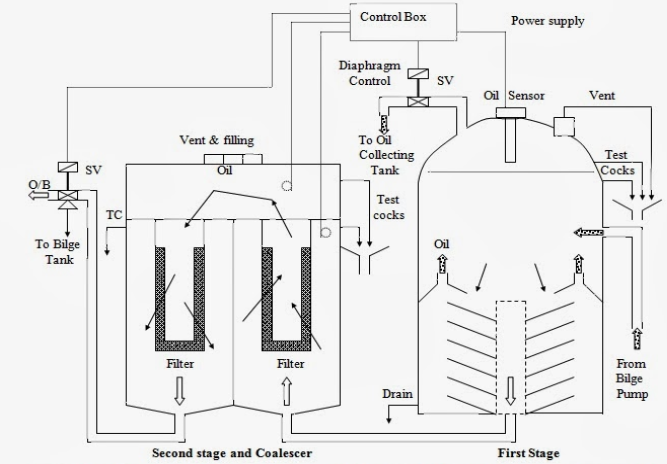
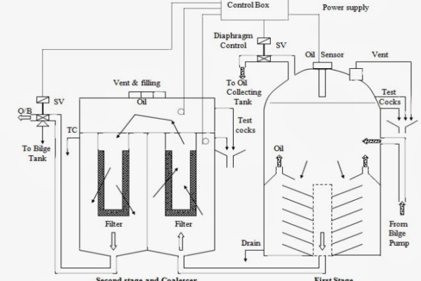
Separator unit
- This unit consists of catch plates which are inside a coarse separating compartment and an oil collecting chamber.
- The oil has a density which is lower than that of the water, which makes it to rise into the oil collecting compartment and the rest of the non-flowing oil mixture settles down into a fine settling compartment after passing between the catch plates.
- After a period of time, more oil will separate and collect in the oil collecting chamber. The oil content of water which passes through this unit is around 100 ppm oil.
- A control valve (pneumatic or electronic) releases the separated oil into the sludge tank.
- The heater may be fitted to this unit for smooth flow and separation of oil and water.
- The first stage helps in removing physical impurities to achieve fine filtration in the later stage.
The Filter unit
- This is a separate unit whose input comes from the discharge of the first unit.
- This unit consists of three stages – filter stage, coalescer stage and collecting chamber.
- The impurities and particles are separated by the filter and settle at the bottom for removal.
- In the second stage, the coalescer induces a coalescence process in which oil droplets are joined to increase their size by breaking down the surface tension between oil droplets in the mixture.
- These large oil molecules rise above the mixture in the collecting chamber and are removed when required.
- The output from this unit should be less than 15 ppm to fulfil discharge criteria.
Oil Content Monitor and Control Unit
- This unit functions together in two parts – monitoring and controlling.
- The ppm of oil is continuously monitored by Oil Content Monitor (OCM); if the ppm is high, it will give an alarm and feed data to the control unit.
- The control unit continuously monitors the output signal of OCM, and if an alarm arises, it will not allow the oily water to go overboard by operating a 3-way solenoid valve.
- There are three solenoid valves controlled by the control unit. These are located in the first unit oil collecting chamber, second unit oil collecting chamber and one on the discharge side of the oily water separator, which is a 3-way valve.
- The 3-way valve inlet is from the OWS discharge, where one outlet is overboard and the second outlet is to the OWS sludge tank.
- When OCM gives an alarm, the 3-way valve discharges the oily mixture in the sludge tank.
Factors affecting the separation of oil from bilge water
- Density: As water has more density than that oil, it tends to rise
- Adequate Density Difference: Seawater has more density than that freshwater. Thus, by using seawater, we can increase the rate of separation.
- The viscosity of Fluid: we know a less dense fluid with less viscosity offers better conditions for oil to move towards the surface than a dense fluid with more viscosity. Here the viscosity of fresh water is less than that of seawater.
- Temperature: It is a significant factor that affects both density and viscosity. When the temperature is low, among fluid particles restricting separation, viscosity is higher.
- Size of particles: The separation of oil from water is directly proportional to the size of oil particles.
What causes an Oily Water Separator to malfunction?
The following causes might result in the separator malfunctioning:
- When the separator has an abnormally high throughput.
- Breakdown of wall globules due to extreme rolling and pitching of the ship
- The pump type and rating is not matching, causing too much turbulence
- Due to the high pumping rate, there is turbulence.
Maintenance
- Ensure that the separator is initially filled with seawater before the bilge mixture is supplied to it. This is to increase the life of filters and also to maintain the operational efficiency of the separator.
- Never discharge or drain water-oil mixture from the separator abruptly out of OWS as it will lead to the separated oil adhere to coalescers, making it inoperative.
- It is advisable to install a dust filter in the inlet line of the OWS
- Keep Viscosity in Limit
- If a heating device is provided, ensure it is ON when OWS is in operation and switched OFF before OWS is stopped.
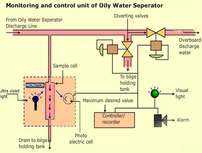
Oil content monitor
- Oil content monitors are used to detect and measure oil content in water.
- It is fitted to the oily water separator and is responsible for ensuring that any amount of oil in the water over 15PPM is alarmed and prevented from being discharged in the sea or river.
Principle
- Ultra-violet fluorescence i.e., the emission of light by a molecule that has absorbed light. During the short interval between absorption and emission, energy is lost and light of a longer wavelength is emitted.
- Oil fluoresces more readily than water and this provides the means for its detection.
Working
A sample is drawn off from the overboard discharge and passes through a sample cell. An ultra- violet light is directed at the sample and the fluorescence is monitored by a photoelectric cell. The measured value is compared with the maximum desired value in the controller/recorder. Where an excessive level of contamination is detected an alarm is sounded and diverting valves are operated. The discharging liquid is then passed to bilge holding tank.