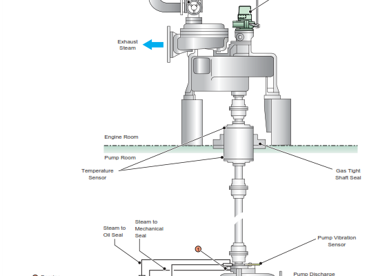
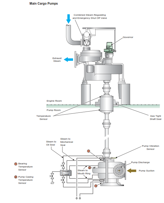
Normally on oil tankers the main cargo pump system consists of three vertical centrifugal single stage double suction type cargo pumps. They are situated at the bottom of the pump room and are driven by a single stage Curtis steam turbine and intermediate shaft passing into the pump room through a gas tight bulkhead gland. The pumps are each equipped with an automatic unloading (stripping) system (AUS) which is optional and may vary on different oil tankers.
Procedure for the Operation of Cargo Pumps
Pre-Operation Checks
a) The chief officer/duty deck officer should notify the duty engineer of cargo pump requirements, giving at least one hours notice. The duty engineer will then make the cargo oil pumps ready for operation.
b) Before the cargo pumps are run up the duty cargo officer is to:
- Ensure the pump discharge valves are closed
- Ensure the pump volute casing and separator chamber are primed
- The pump and line suction valves are fully open
Pump Starting
The operation for bringing the cargo oil pump turbines up to minimum speed is carried out at the turbine side by the duty engineer. Only after this point will command of the pumps be passed over to the chief officer/duty deck officer in the CCR. Initially the steam lines to the turbines are drained of any water and the casing warmed through. After this period, each turbine is spun at approximately 100 to 200 rpm for approximately 25 minutes, when this period has elapsed and no faults found, each pump will be tripped.
After the trips have been reset, the turbines are run up to the minimum speed setting where the governor will take over control of the speed. This period will take approximately 15 to 20 minutes. If all is satisfactory, the duty engineer will then inform the chief officer/duty deck officer that control can now be carried out from the CCR. The turbine trips can now be verified from any of the four outstations positions. The emergency stop buttons in the CCR on the main console and at the bottom of the pump room are trips for the individual pumps rather than as a group.
Note: The warming up period at low revolutions is kept to a minimum, sufficient to ensure that condensate is expelled before the pump speed is increased. Extended operation at low revolutions could lead to overheating of the final stages of the turbine and local uneven heating of the casing.
a) During the warming up period if the pump discharge pressure rises above 0.5MPa open the pump discharge valve gradually to limit the pressure increase.
The duty engineer will check that there is no abnormal noise or vibration in the turbine and the reduction gear. If an abnormal state is noticed, the turbine will be stopped immediately and the problem investigated.
b) The duty engineer will trip the turbine(s) by operating the hand trip knob to confirm that the governor control valve closes immediately. The trip will then be reset. Ensure that the pump discharge valve is shut before the pump is run up again.
c) The pump discharge valve should be shut before the duty deck officer tests the emergency trip mechanism of each pump on the cargo console in the CCR or at one of the outstation trip positions. The duty engineer will reset the trip when the turbine is fully stopped and the speed setting is at minimum. The pump(s) will then be restarted as required.
Pump Stopping
a) Inform the duty engineer that a COP is about to be stopped then decrease the turbine speed gradually down to minimum speed.
b) Stopping is possible by operating either a remote emergency stop at one of four outstation positions, the individual cargo oil pump turbine STOP button on the CCR cargo console or at the pump room bottom plates level or the hand trip on the turbine. The pump discharge valve should be shut before the pump turbine is stopped.
c) Close the pump suction valves.
Emergency Stopping
Local Stopping
Pull the hand trip knob so that the spindle moves outward and the governor valve closes through activation of the trip mechanism causing the turbine to stop.
Remote Stopping
Press the remote stop buttons provided at the remote stop stations so that the trip mechanism activates to close the governor valve and stop the turbine, the remote stops are located at the following locations:
- Outside of the pump room entrance, port and starboard sides
- Pump room bottom plates
- Midship manifolds after end, port and starboard
- CCR cargo console
Resetting the Emergency Trip
Before resetting the emergency trip, ensure the following conditions are fulfilled:
- The pump is at the minimum load, i.e. the pump discharge valve is fully closed.
- The governor speed setting is at the minimum speed.
- The turbine steam inlet valve is fully closed and the turbine is stopped.
Operating Procedure of the Remote Control System
With the individual pumps and separators primed, open the pump suction and required tank suction valves.
Lamps are fitted for indication of an alarm and/or trip condition. The actual trip or alarm condition is indicated on the control panel at the turbine side. Indication is given on the control panel of pump speed, discharge pressure and suction pressure.
During control from the CCR, the speed of the turbine is controlled by an increase/decrease lever which send a signal to the turbine governor. The discharge rate from the pump is controlled both on the speed of the turbine and the position of the pneumatic controlled discharge valve. When at the stripping stage, the pneumatic controlled discharge valve should be under the control of the AUS in order to maintain the back pressure on the pump while at the same time ensuring that the separator level is maintained as high as possible. If AUS is not fitted then control the pump main discharge valve.
The pump is normally stopped by reducing the speed to the minimum setting and pressing the STOP button on the cargo console control panel.
Reset for the trip and alarm functions is provided at the turbine side. An hours run indicator is provided on the control panel.
CAUTION:The manufacturer’s casing temperature set point of 80ºC will be suitable for cargoes of all temperatures, but if a non-heated cargo is carried, it is advisable to reduce the set point to some 20ºC above the ambient cargo temperature. This will give early warning of system abnormalities and lessen the likelihood of damage to the pump seals.
Alarm and trips for the cargo pump/turbines are as follows:
- Overspeed trip, electrical and mechanical, 113% and 115% respectively
- LO low pressure alarm, 60kPa
- LO low pressure trip, 50kPa
- High LO temperature alarm, 53°C
- LO tank low level alarm
- High exhaust steam back pressure trip, 100kPa
- Pump casing high temperature trip, 80°C
- Pump bearing high temperature trip, 90°C
- Pump pressure discharge high trip, 1.59MPa
- Bulkhead stuffing box high temperature trip, 80°C
- Low inert gas pressure trip, 100mm WG
- Excessive axial movement of the turbine rotor trip, 0.7mm
CAUTION: Running the pump in the manual condition i.e. with the automatic stop of the pump at finish of stripping deactivated, may result in the pump running dry, or running with the discharge valve closed longer than the manufacturer’s recommendation. This may result in serious damage to the pump and its mechanical seals.
Shaft Seal Cleaning
When heated cargoes are carried, it is necessary to carry out a cleaning operation of the cargo pump seals and impellor rings after the cargo operations have been completed and the pump turbines stopped and fully shut down.
When steam cleaning of the pump seals and rings is to be carried out, ensure that the steam line is drained of water. The steam pressure during cleaning should be approximately 0.2 – 0.3 MPa, with a cleaning time for each pump of 10 minutes. During the cleaning period, the pump(s) shaft should be turned by hand from the engine room.