Typical domestic refrigeration system on board a ship
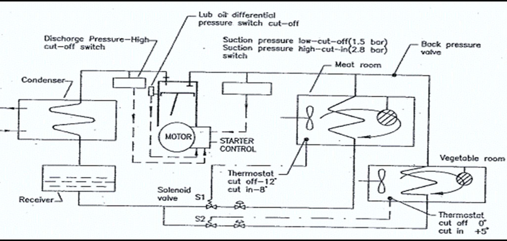
- Once the room is loaded, for example meat or vegetable, the liquid refrigerant at the evaporator coil will pick up the heat from meat and vaporise.
- Vapour pressure at compressor suction will increase and ‘suction pressure high’ (2.8 bar) switch will actuate the motor started and the motor will cut in.
- Now the compressor will run and draw gas from evaporator coil and pumping refrigerant liquid back to the evaporator coil through condenser and expansion valve.
- The plant will continue to operate in the aforementioned cycle until the meat room temperature reaches a set value say -12°C.
- At this point, the thermostat will cause the solenoid valve S1 to shut off and this stops the flow of liquid refrigerant to the evaporator.
- Also, the suction pressure at the compressor inlet will drop and compressor will cut off on ‘low suction pressure’ (1.5 bar).
- Again, when the room temperature rises to a set value say -8°C, the solenoid valve will open and stored liquid refrigerant in the receiver will flow into the evaporator coil and vaporise absorbing heat.
- Now the ‘suction pressure high’ switch will again actuate and the compressor starts to take vapours from the evaporator coil. This way the cycle is repeated.
Safeties in the domestic refrigeration system
- High pressure cut-outs
- Low pressure cut-outs,
- Oil failure cut-outs,
- Safety valves or busting discs
High Pressure Cut-Outs:
- It is fitted at the delivery of the compressor. If the compressor delivery pressure increases above the set value,then the compressor trips.
- It requires a manual reset to start the compressor.
Low Pressure Cut-outs:
- The low pressure [LP] cut out trips the compressor in case the suction pressure drops below the set value.
- In most of the plants, it is used for starting and stopping the compressor to maintain the temperatures.
Oil Failure Cut-Outs:
- The luboil differential pressure cut out compares the luboil pressure and the suction pressure of the compressor.
- If the differential pressure falls below 1.2 bar, then the compressor trips and requires a manual reset to restart.
- A time delay is built into the circuit to allow sufficient time for the luboil pressure to build up while starting.
Safety Valves or bursting discs:
- Bursting discs are fitted internally between discharge and suction manifolds on many compressors.
- Double bursting discs, with a pressure gauge connected between them are sometimes used to protect the high- pressure side of the system.
- The reason for fitting two discs is that eventually discs develop slight leaks, caused by fatigue and the refrigerant charge can slowly leak. Gauges should be inspected daily and should read zero.
- If any gauge shows a reading, the first of the pair of discs is leaking and should be replaced.
How is refrigerant leakage detected? What is the storage temperature of Vegetable, Meat and Fish in general?
Leak detection:
Indications:
- Time taken for the temperature of the room to come down is longer than usual.
- Plant is hotter.
- Compression suction side is warmer
- Running hour is more for the compressor.
Detection:
- Regular inspection of all components of the refrigerant circuit must be made.
- Examine for traces of oil, wherever oil is weeping, refrigerant will also be being lost.
- Attention should be concentrated on compressor glands, flanges and pipe joints, particularly the flared ends of copper pipes.
- A most thorough test is to paint over all joints with a soapy water solution and look for bubbles.

Detector Lamp:
- For freon plants, leak detector lamp is used.
- Lamp consists of fuel tank, an exploring tube, reaction plate, flame shield and needle valve
- The end of the exploring tube must be traversed slowly round all joints, keeping close to and preferably touching the pipe.
- Traces of freon picked up by the exploring tube gives the flame a pale green hue changing to violet for higher concentrations.
- Ventilation with fresh air is necessary to dilute the escaped freon and allow the leak to be pinpointed.
- If the space is not ventilated, freon gas might have accumulated in the locality and flame will keep showing pale green hue and pin pointing leak detection becomes difficult.
Temperature:
For meat room – -8 to -12°C
For vegetable room 0 to +5°C
How critical temperature restricts plant operation and how these limitations overcome
Critical Temperature:
- The critical temperature (Tc) is the temperature above which a refrigerant cannot exist in its liquid state, regardless of the pressure applied.
- At the critical temperature, the liquid and vapor phases of the refrigerant become indistinguishable from each other, and the distinction between liquid and gas phases disappears.
Limitations:
- The critical temperature imposes limitations on the operating conditions of the refrigeration plant, particularly on the condensation process.
- In conventional vapor compression refrigeration systems, the refrigerant must be condensed from its vapor phase to a liquid phase to reject heat effectively.
- However, once the refrigerant temperature approaches or exceeds its critical temperature during the condensation process, it cannot fully condense into a liquid.
- Instead, it remains in a supercritical state, leading to reduced efficiency and cooling capacity of the system.
Steps to overcome:
- Refrigerants with critical temperatures higher than the operating conditions are chosen for specific applications.
- These refrigerants allow for effective condensation at the desired temperature range and maintain optimal system efficiency.
- Subcooling is a process that involves cooling the refrigerant below its condensation temperature after the condenser to ensure that it remains in its liquid state before entering the expansion valve.
- Subcooling helps prevent any superheating and ensures more efficient evaporation in the evaporator.
- Cascade refrigeration systems use two or more refrigerants with different critical temperatures in separate cycles.
- These systems allow for efficient cooling even in cases where the critical temperature of one refrigerant is too close to the desired condensation temperature.
Typical cargo hold refrigeration system. What is the role of the secondary refrigerant?

- Using primary refrigerant through the cargo spaces is not feasible and also it can escape to minute clearances.
- Secondary refrigerants are employed where the installation is large and complex such as in reefer ships.
- Brine which is made by mixing ¼ kg of calcium chloride in 1 litre of fresh water is used as secondary refrigerant.
- Primary refrigerant vaporises at the evaporator coil causing brine to cool.
- Brine gets cooled to about -15°C and is circulated to the reefer holds.
- By controlling the flow rate of brine through each hold at the return valves, we can control the temperature of any hold.
- As the percentage of calcium chloride is increased, the freezing point of the brine will decrease.
- Thus, depending on lowest temperature, the brine will experience, percentage of chloride may be adjusted in calcium chloride water mixture.
- Inhibitors to prevent corrosion are also added.
Various reasons for such a refrigeration system to become less efficient
Reasons for reduced efficiency
- Ingress of external heat through open door or open drain.
- Any fouling, scaling, or poor maintenance can reduce heat transfer efficiency.
- If the temperature difference between primary refrigerant and secondary refrigerant is high, it will impact the system’s efficiency.
- Leaks can lead to reduced cooling capacity and increased energy consumption, resulting in reduced efficiency.
- The piping and components of the secondary refrigerant loop must be adequately insulated to prevent heat gains and losses.
- Poor insulation can cause thermal losses and impact the overall efficiency of the system.
- Oil contamination can occur in the secondary loop due to leaks or improper system design, affecting heat transfer and reducing efficiency.
- wear and tear, component degradation, and reduced system performance.
How bacteria can be transmitted throughout the air conditioning unit / what measures are taken to maintain the system in an acceptable sterile state /What are the advantages of using double duct system over single duct system for air conditioning?
Transmission of bacteria:
- Certain types of bacteria grow and multiply in the air conditioning system of the ship.
- Ideal conditions for these bacteria to grow is wet deposits or stagnant water.
- These bacteria are known as legionella bacteria.
- Common areas are air inlets, filter, cooler units/dehumidifier, and humidifier.
- These bacteria cause legionnaire disease and it is a type of pneumonia.
- This disease can be fatal to people, especially to the elder ones.
Measures to prevent:
- Regular inspection and cleaning of the filters and similar parts.
- Cleaning can be done using 50 ppm super chlorinated solution used as a sterilizing agent.
- Such solution is also to be used on the cooler drain area at not more than three months intervals.
- This sterilization is necessary for water spray type humidifier in air conditioning system.
- Steam spray humidifier are to be preferred over water spray humidifiers.
- Proper attention should be given to efficient drainage.
- The sump drains should be regularly inspected and cleaned.
- The sump can also be washed using super chlorinated solution.
Advantages:
- Total airflow rate to each zone is constant, thus it is possible to maintain air distribution.
- Cooling in some zones and heating in other zones can be achieved simultaneously
- System is very responsive to variations in the zone load, thus it is possible to maintain required conditions precisely.
- The double duct system provides good temperature and humidity control.
- This system accommodates a variety of zone loads.
- The system is flexible in nature; thus, zones can be added or sub-divided.
- Due to this flexibility, this system is mainly used in passenger ships.
Functions of an expansion valve fitted in the system

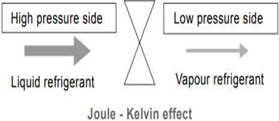
- When the refrigerant flows from through an orifice, i.e. from high pressure side to low pressure side, there is a drop in pressure.
- This causes the saturation temperature of the refrigerant to fall below its actual temperature.
- As a result, some of the liquid boils off at the orifice by taking latent heat from the remaining liquid.
- The corresponding drop in liquid temperature causes the refrigerant to change its phase from liquid to vapour.
- The thermostatic expansion valve allows the refrigerant to expand at a controlled rate, depending on the load.
- The valve measures the exit temperature of the refrigerant from the evaporator and controls the refrigerant flow to the evaporator so that the liquid completely changes to vapour before leaving the evaporator.
- Expansion valve consists of a valve body with valve seat, a thermostatic element separated from the valve body by a diaphragm and spring.
- A capillary tube connects the element to the bulb.
- In larger plants where pressure drop in evaporator is more, an equalising or balancing line is provided.
- This connects the evaporator outlet to the lower side of the diaphragm.
- This eliminates further increase in superheat temperature to compensate for reduction in pressure and so allows an increase in effective area of the evaporator.
Vapour compressed AC system
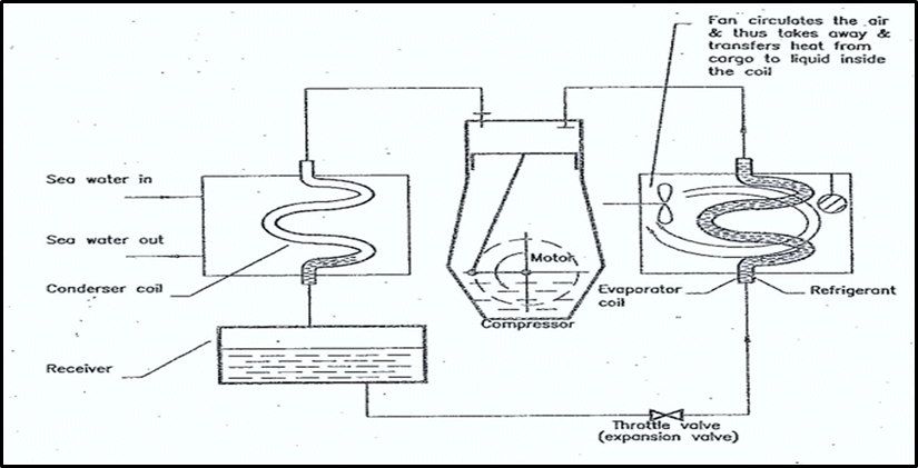
Vapour Compression Cycle:
- The refrigerant initially at low temperature and low pressure.
- The pressure of the refrigerant gas is increased in the compressor, during which it gets heated.
- The hot and high-pressure gas enters the condenser, where sea water is used for cooling the gas.
- The cooling causes the high-pressure gas to become liquid and it is stored in the receiver.
- This liquid is under high pressure and led to an expansion valve.
- In the expansion valve, the sudden drop in pressure causes liquid to flash off into a gas, in the process it absorbs heath from the surroundings.
- This is the refrigerating effect, which takes place in the evaporator coil.
- Now the gas is once again pressurised in the compressor, and the cycle repeats itself.
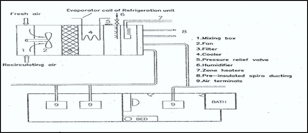
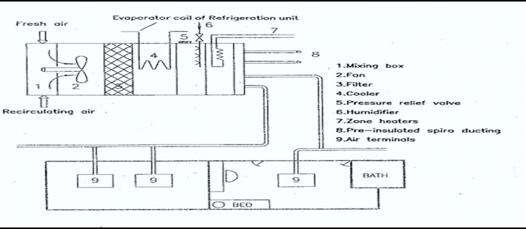
Double duct system
- Two separate ducts are run from the central unit to each of the air terminals,
- In winter, two warm air streams of differing temperatures are carried to the air terminals for individual mixing.
- The temperatures of both the air streams are automatically controlled.
- All the air is first cooled and dehumidified, then divided into two ducts.
- One cold air duct and a parallel warm air duct, distributes air from the central air handler to the conditioned spaces.
- Dual duct system provides good temperature and humidity control.
- Provides the option of adding or subdividing zones in future.
- Initial cost for set up is high. And energy consumption is also high relative to single duct system

Single duct system
- Single duct system is widely used on cargo ships.
- Several central units are used to distribute conditioned air to a number of cabins or spaces via a single pipe or duct.
- In warm climates a mixture of fresh and recirculated air is cooled and dehumidified (some water removed) during its passage over the refrigeration unit.
- In cold climates the air mixture is warmed and humidified (some water is added) either by steam, hot water or electric heating.
- The temperature and humidity of air is controlled automatically at the central unit.
- Within the conditioned space, control is by variation of the volume.
Defrosting cold room? Why defrosting is done? How it is done?
- Defrosting a cold room on ships is a process of removing the accumulated ice and frost from the surfaces of the cold room, particularly the evaporator coils of the refrigeration system.
- Cold rooms are used on ships to store perishable goods and maintain them at controlled temperatures to prevent spoilage during transportation.
Why is defrosting done?
- Over time, if this frost and ice are not removed, it can reduce the efficiency of the refrigeration system, hinder proper airflow, and increase energy consumption.
- This can lead to inadequate cooling and potential spoilage of the stored goods.
How is it done?
- Defrosting on ships can be done manually or automatically, depending on the type of refrigeration system in use.
Manual defrosting:
- In some older or smaller ships, defrosting might be done manually.
- This involves shutting down the refrigeration system and allowing the ice to melt naturally.
- The water resulting from the melting ice is drained away through a designated drainage system.
- This process can be time-consuming and may require careful planning to ensure minimal impact on the stored goods.
Automatic defrosting:
- Modern ships are equipped with refrigeration systems that often have automatic defrosting features.
- These systems periodically reverse the operation of the refrigeration cycle to heat up the evaporator coils.
- The heat melts the frost and ice, turning it into water.
- The water is then drained away, and the system returns to its normal cooling cycle.
- The frequency of defrosting depends on factors such as the operating conditions, the type of goods being stored, and the efficiency of the refrigeration system.
- Some systems might defrost every few hours, while others may do it once a day or as needed.
- In both cases, it’s essential to ensure proper drainage to prevent water accumulation in the cold room, as excess water can lead to mold growth and compromise the condition of the stored cargo.
Important properties of a refrigerant? State the refrigerants used for refrigeration on board ships
- It must be possible to compress the refrigerant at low pressure at the compressor. Thus, condensing pressure for the vapours of the refrigerant should be low.
- Once the evaporated gas is compressed, the temperature of seawater should be low enough (below critical temperature of the refrigerant) to condense these gases to liquid form.
- Thus, critical temperature of the refrigerant should be high.
- The liquid at the evaporator coil should vaporise easily, otherwise the compressor have to create too much vacuum to cause the liquid to vaporise.
- Thus, the boiling point of the refrigerant must be low.
- Vapour produced after vaporisation of liquid at the evaporator coil should occupy minimum volume to keep the pipeline diameter, compressor size etc. small and compact. Thus, refrigerant vapor should have low specific volume.
- The liquid refrigerant that gets vaporised in the evaporator coil should be capable of taking large amount of heat. Thus, the specific enthalpy of vaporisation (latent heat) of refrigerant should be high.
- It shall be non-corrosive, non-toxic, non-flammable and non-explosive.
- It shall be stable, easy leak detection must be possible.
- Compatible with crank case oil, oil seals, gaskets, metals involved etc.
- It must be cheap, easily available and easily stored.
Refrigerants Used:
- Most of the modern refrigerants are Chloro-Fluro-Carbons which have a damaging effect on the ozone layer.
- It also accumulates in the atmosphere and causes global warming.
- R11 is a low-pressure gas and hence large circulation of gas is required for the given cooling effect, but consumes very low power
- R 12 is substantially available at low price, but its pressure goes below after the evaporator and if there is a leak in the system, it draws, air and moisture into the system
- CFC-12 or freon-12 are replaced by HFC 134A which causes zero ozone depletion.
- R-22 or HCFC–22 is used in almost 90% of ships as it is relatively a less harmful gas.
- R22 highly useful for low temperature operation and due to this a small quantity is required to bring the desired temperature, making the whole unit less in size and power requirement goes down
- The mixture of R22 and R 115, gives us R502, which is a fixed boiling point refrigerant.
- Similar to R22, R502 requires a smaller component but its temperature after the compressor is comparatively low and does not breakdown the Lube oil properties and also no temperature induced stress on the delivery valves. But this is more expensive due to its non-availability