Preamble
It is just not possible to know every ship in its details. In order therefore that officers and engineers are in a position to acquire more information, the ship builder and the shipowner provides plans and other details about the ship on board. These plans like the general arrangement plans are available as they are displayed in the alleyway. However there are a number of other plans for which we need to keep our eyes open and find where they are. Information provided in these plans is for reference purposes. especially in an emergency.
Objective
To recognise various types of plans used on a ship. Every ship is the final result of thousands of hours of hard work put in by hundreds of dedicated professionals. Right from the beginning, several drawings usually referred to as ‘plans’ are drawn covering various aspects of ship construction. In shipyards, the section that has the responsibility of making these plans is called the Drawing Office’.
Naval architects and draughtsmen from this office work in close co-operation with the owner and various other departments offices, within the shipyard and outside, to make sure that the construction of the vessel progresses as per pre determined design and schedule.
To achieve the above target, the drawing office turns out plans in large numbers. All plans besides having several details and considerable information have in bold letters, usually a rubber ‘chop’ in red, indicating the type of the plan. For example:
‘FOR OWNER’S APPROVAL’
‘FOR COMMENTS & APPROVAL OF DESIGN DEPARTMENT’
‘FOR CLASS APPROVAL’
`FOR OUTFIT DEPARTMENT’
`FOR SUB-CONTRACTOR’
`FOR REFERENCE ONLY’
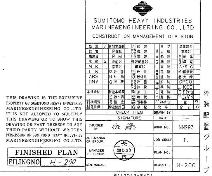
`FINISHED PLANS’
On your vessel you will find almost all the plans are marked as ‘Finished Plan’. This is so because once the vessel is delivered and is operating , no more approvals, comments and references are required. The details of the vessel as constructed, i.e. ‘Finished’, only need to be recorded and given to the vessel and her owners. The Master and Officers on board and the Superintendents in the Owner’s / Manager’s office ashore will therefore have the copies of ‘Finished Plans’ only. But sometimes due to very special reasons and at times due oversight too, some other than ‘Finished Plans’ may also be found on board.


Yet another stamp that you may come across on plans could be ‘Approved’. This stamp is given by an office in authority, which certifies that the ship as shown in the plan meets certain minimum requirements under set out laws.

CAUTION: Whenever you refer to any plans, always verify the ‘Finished Plan’ stamp first.
Recognising Plan Area Details
Before we look into the detailed information contained in the plan, it is of importance to first confirm that the details we are looking for are actually contained in that plan. To achieve this target, all plans, without exception, would contain a rectangular ‘field’, called the ‘Address Key’, on the right hand bottom corner; giving vital details about the plan itself. The address key would include:
Heading of the plan.
‘GENERAL ARRANGEMENT’
‘LINES PLAN’
‘SHELL EXPANSION PLAN’
`CAPACITY PLAN’ etc.
The heading is given in the largest of the fonts.
Vessel’s name –
There is absolutely no confusion about this. You should only find plans of your ship on board your vessel. This information is also in large font.
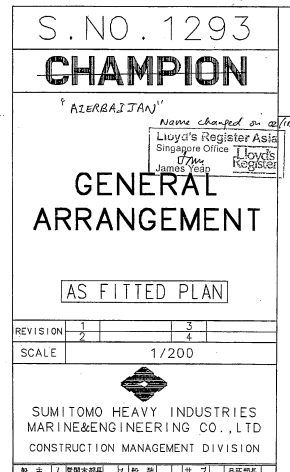
Hull No. —
A vessel is known by her name after she comes into operation but the shipbuilding yard knows a vessel by her hull number. The vessel name may change a few times during her life span; her hull number would always identify her correctly to her place and date of build.
Scale –
All plans show information of large area on a much smaller paper area. The size therefore has to be reduced in the same proportion to maintain correct conception and easy understanding. The ratio of reducing the size on paper from actual dimensions to the size shown is the scale. A scale of 1:200 is very common for very many plans on ships. This means that a centimetre on the plan is 200 centimetres on the actual ship.
The scale at times is referred to as the ‘Drawing Scale’ or ‘Natural scale’ too. Do you remember the natural scale? We use it for navigation charts also.
Drawing No. —
Another piece of vital information from the user’s point of view is the drawing or plan number. This helps in the indexing, identification, listing, retrieval and storing of plans.
Minor details —
The ‘minor’ details are minor only from the user’s point of view. They include the name of the office where the drawing was prepared, the name, or the Code number of the person who prepared the drawings, checked them and gave final OK for putting them into effect along with respective dates.
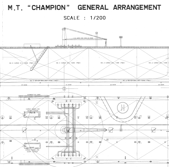
The ‘Heading’ of the plan and the ‘Scale’ are also shown on the top Centre of the plan to make them more conspicuous.
Recognising Vessel Data
We have learnt so far about the heading and the address key on plans,Let us look at the main body of the plans where the real information is Contained.
Plans contain a large amount of information pertaining to specific area or particular machinery/equipment of the ship. Learning about all of them would be rather out of place for now, so we will look at some of the common plans and their details that would be of interest to you.
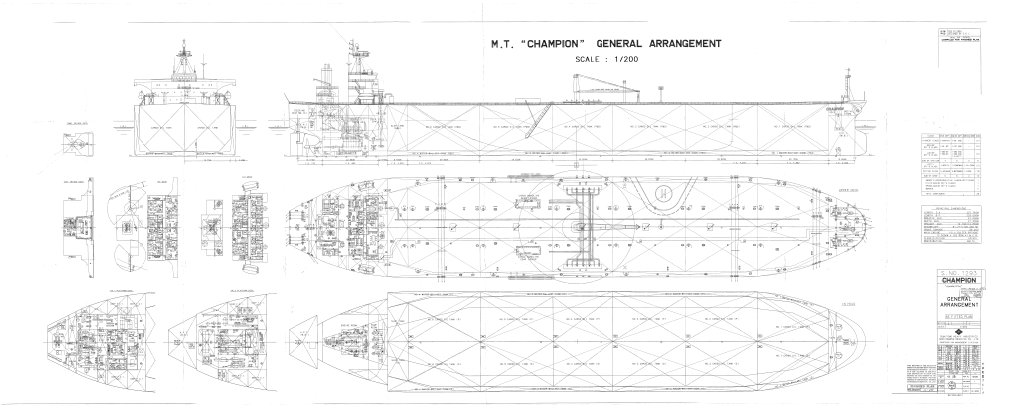
The General Arrangement plan, as the name suggests, contains the layout of the ship in general. It will show the ship form, outlined in profile as well as in plan. The plan for all decks (forecastle, accommodation block, & 1st Platform Deck, 2nd Platform Deck etc. in the machinery space) is also included.
The General Arrangement plan or the GA plan as it is commonly known as, is the first plan that any one refers to, for getting a general overview of the vessel.
It is used very frequently hence by regulations; it is required to be displayed within the ship where it can be referred to quickly, usually in one of the alleyways.
Look at your ship’s GA plan and look closely at the weather deck in plan view. In the centre you will find a line running all along the entire ship’s form, graduated like a scale of a ruler and also marked with some numbers which keep increasing from aft to forward. The numbers shown are the frame numbers which always increase from aft to forward, and are helpful in locating a particular item: say a valve or a pipe which, as per the plans is located between frames 27 & 28 can be easily traced using the frame numbers.
The Capacity Plan. Again the name given to this plan reminds us of its most important use. The capacity plan gives the volume i.e. the cubic capacities of various spaces that are used for holding cargo, fresh water, ballast water, bunkers, lubricating oils, etc.
Safety Plan (sometimes called the Life Saving Plan & Fire fighting plan) is yet another plan that you would find displayed in the alleyways. In this plan you would find details pertaining to Safety.