
Why is it necessary to treat the sewage generated on board?
Reason for treatment of sewage:
- Untreated sewage as a suspended solid is unsightly.
- When discharged without treating, in order to break down naturally, raw sewage must absorb oxygen.
- In excessive amounts it could reduce the oxygen content of the water to the point where fish and plant life would die.
- Pungent smells are also associated with sewage as a result of bacteria which produce hydrogen sulphide gas.
- Particular bacteria present in human intestine known as coliforms are also to be found in sewage.
- They are not normally harmful, except when they contain pathogenic colonies which can cause dysentery, typhoid, para-typhoid, etc.
Treatment before pumping:
- Two particular types of sewage treatment plant are in use, employing either chemical or biological methods.
- The chemical method is basically a storage tank which collects solid material for disposal in permitted areas or to a shore collection facility.
- The biological method treats sewage so that it is acceptable for discharge in shore.
Chemical Treatment Method (Disinfecting and communiting plant):
- This has an initial reception chamber, in which separation of liquid and solid sewage takes place.
- Waste drops onto the moving perforated rubber belt, driven by an electric motor.
- The liquid pass through, but the solids travel with the belt to a caustic treatment plant.
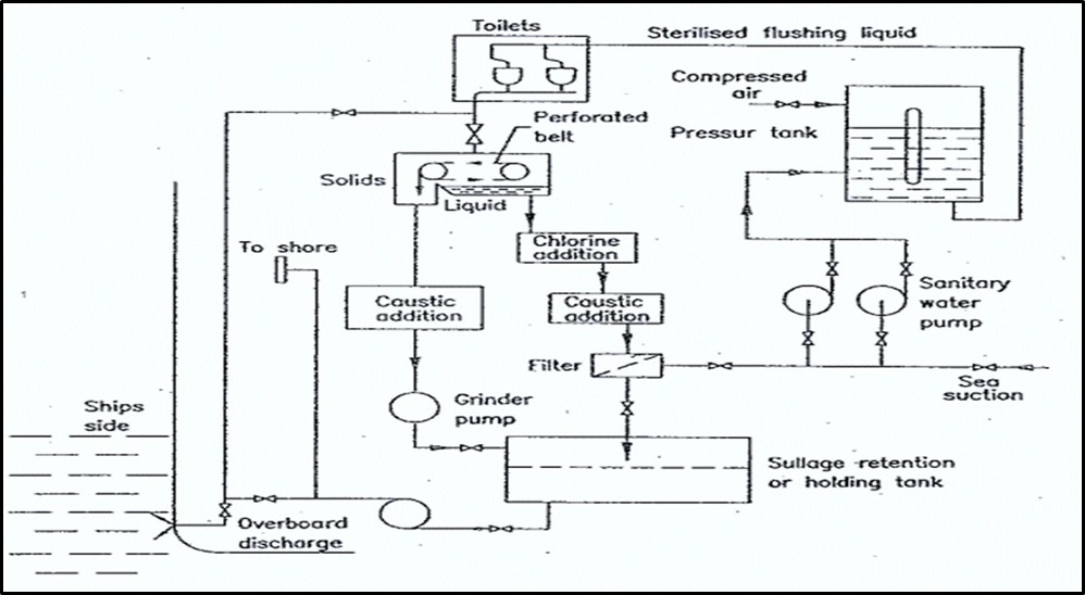
- Solids are chemically inerted by caustic compound and delivered via grinder pump to the holding tank.
- Liquid is treated with chlorine and causting based compound so that liquid effluent is accpetable for use as flushing liquid.
- Incorrect chemical dosage may cause chemical odour of the flush water and may result in high alkalinity leading to corrosion.
Functioning of a biological sewage treatment plant
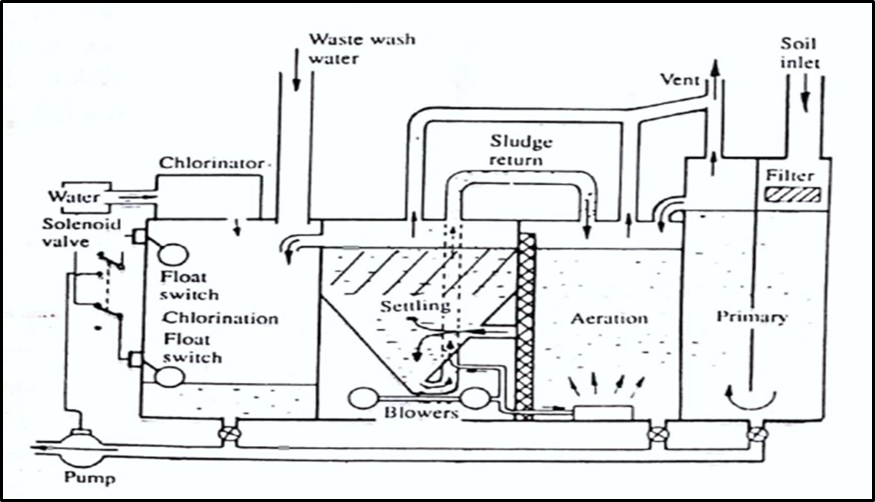
- The treatment plant uses a tank which is divided into three watertight compartments
- An aeration compartment,
- A settling compartment and
- A chlorine contact compartment.
- Incoming waste enters the primary chamber through coarse screen.
- The primary tank overflows into the aeration compartment.
- The breakdown of waste matter takes place in aeration compartment, by bacteria which consumes the waste and require oxygen which is provided by air compressor.
- After prolonged aeration, the mixture is displaced into the settling tank.
- Biological floc is formed in the settling tank.
- Activated sludge gravitates to the bottom and continuously withdrawn and returned to the aeration chamber to mix with the incoming waste.
- This is done by means of air lifter where air supply is provided by compressors.
- Clean effluent from the top of the settling compartment is collected in the last chamber, for disinfection and discharge over board.
- Float switches control the discharge pump.
- The chlorinator ensures that the water is sterilised.
Regulation for condition and discharging sewage overboard
Discharge of sewage from ships other than passenger ships in all areas and discharge of sewage from passenger ships outside special areas:
- If a ship is fitted with comminuted and disinfected sewage system approved by the administration, then the sewage can be discharged at a distance of more than 3 nautical miles from the nearest land.
- Sewage which is not comminuted or disinfected can be discharged at a distance of more than 12 nautical miles from the nearest land.
- In both the above cases, vessel must be En-route and proceeding at not less than 4 knots and rate of discharge shall be approved by the administration.
- Or if the ship has an approved sewage treatment plant, the effluent shall not produce visible floating solids nor cause discoloration of the surrounding water, the sewage can be discharged anywhere provided that in compliance with local regulations if any.
Discharge of sewage from passenger ships within a special area:
- If the passenger ship has an approved sewage treatment plant and the effluent shall not produce visible floating solids nor cause discoloration of the surrounding water, the sewage can be discharged anywhere provided that in compliance with local regulations if any.
- If the passenger ship does not have an approved treatment plant, then discharge of sewage is prohibited in special area which is the Baltic sea.
General Requirement:
- When the sewage is mixed with wastes or waste water covered by other Annexes of MARPOL, the requirements of those Annexes shall be complied with in addition to the requirements of this Annex
Biological sewage system develops a fault which necessitates opening the unit for repair /The risk associated with opening the unit /The precautions taken to reduce the risk
Risk associated with opening the unit:
- When the sewage treatment plant is stopped and sewage is left in the tank, the sewage will go bad resulting in the production of poisonous hydrogen sulphide gas.
- The inhalation of the gas may cause death.
- The space is a confined space and lack of oxygen is definitely a possibility.
- Exposure to micro-organisms can cause serious ill effects.
- Inadvertent energizing of machine is another risk.
- Slip, trips and falls are common hazard when working on sewage treatment plant.
- Another major hazard is accidental contact with the high voltage current.
Precautions taken to reduce the risk:
- When the unit has to be opened, open all drain valves located at the bottom while running the aeration blower.
- Discharge all sewage in the plant by using the discharge pump.
- Cleaning water should be used to fill the plant after the covers are removed.
- Flush and drain two or three times confirming that the inside of the plant is clean and empty. Ventilate for some time.
- Check the content of oxygen, hydrogen sulphide and other toxic gases.
- Follow complete enclosed entry procedures.
- The above procedures will eliminate hazards of lack of oxygen, presence of H2S gas and contact with micro- organisms.
- Make sure ventilation is continued through out the maintenance period.
- When working on discharge pump, pipe, valve etc… put on a lock out tag out or similar notice to prevent switching on the system.
- In climbing on the sewage treatment tank, wear a helmet and the gloves and proper safety shoes with anti-slip function.
- When working aloft, wear appropriate PPE and in strict compliance with working aloft procedures and permit.
- The work for maintaining and checking the inside of the control panel should carried out by electrician with expert knowledge so as to prevent any accidental contact with the high voltage current.
Oily water separator for Engine Room bilges
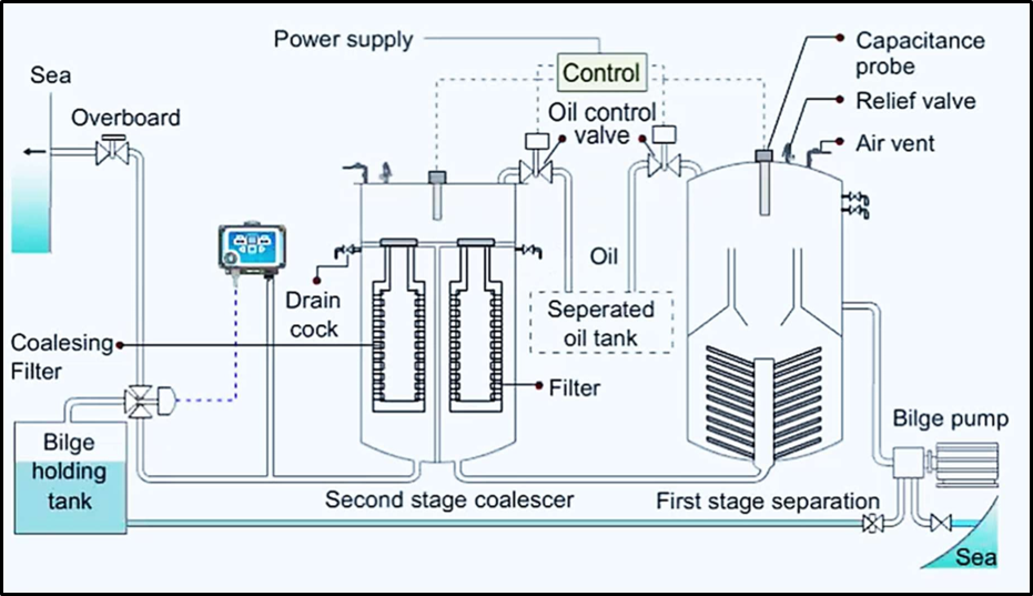
Working of OWS:
First Stage Separation
- The complete unit is first filled with clean seawater. The oily water mixture is then pumped through the separator inlet pipe into coarse separating compartment.
- Here some oil, as a result of its lower density, will separate and rise into the oil collection space.
- The remaining oil/water mixture now flows down into the fine separating compartment and moves slowly between the catch plates.
- More oil will separate out on to the underside of these plates and travel outwards until it is free to rise into the oil collecting space.
- The almost oil free water passes into the central pipe and leaves the separator unit.
- The purity at this point will be 100 ppm or less.
- Automatically controlled valve releases the separated oil to a storage tank.Air is released from the unit by a vent valve.
- Steam or electric heating coils are provided in the upper and sometimes the lower parts of the separator, depending upon the type of oil to be separated.
- Heating reduces viscous drag of oil and thus makes separation of oil and water easier.
Second Stage Separation:
- The water flows in turn through two filter stages and the oil removed passes to oil collecting spaces.
- The first filter removes physical impurities present in the water and promotes some fine separation.
- The second filter uses coalesce inserts to achieve the final de-oiling.
- Coalescence is the breakdown of surface tension between oil droplets in an oil/water mixture which causes them to join and increase in size.
How will you ensure efficiency of oily water separator?
Steps for efficient OWS:
- Ensure that the separator is initially filled with seawater before the bilge mixture is supplied to it.
- This is to increase the life of filters and also to maintain the operational efficiency of the separator
- The OWS is designed to separate small quantity of oil in relatively large quantity of water.
- Thus, if we know a large quantity of oil exists and only very small portion of water may be present, do not pass through OWS, directly transfer the mixture to sludge tank.
- Avoid using highly viscous oil as it will clog the filter. Keep the viscosity of oil within 1000 mm2/s.
- If the bilge mixture contains dust and sand, its difficult to pass through the filter due to their sizes.
- This will reduce the operating hours of the filter and in-turn the efficiency of the OWS.
- If a heating device is provided, ensure it is ON when OWS is in operation and switched OFF before OWS is stopped.
- In case when the OWS is run for a long time, keep a track on the heater for overheating of coils.
- Frequent checks on effluent to be done to assess the performance of the separator.
- If the effluent is found contaminated, immediately stop the separator and take preventive actions
Factors which can lead to improper functioning of OWS.
- The principle of separation on which OWS function is gravity differential between oil and water.
- If oil globules size is larger, temperature of the system is higher and seawater is present, then high rate of separation can be achieved.
- Since, the rate of separation depends on the oil globule size, disintegration of oil globules should be prevented.
- If it gets disintegrated, it will affect the proper functioning of the system as rate of separation will be slow.
- Thus, use of centrifugal pumps as supply pump to separator should be avoided.
- This is due to the fact that they churn the supply and produce small oil droplets.
- A positive displacement pump e.g. slow running double vane, screw, reciprocating or gear pump is favoured which aids in better performance.
- Therefore, following factors affect the proper functioning of OWS: –
- When quantity of small oil globules is excessive,
- When excessive rolling and pitching of the ship causing disintegration of oil globules
- Type of pump used that causes too much turbulence
Important regulations as per MARPOL regarding pumping out machinery space bilge water in open sea and in a special area.
Discharges outside special areas except in Arctic waters
Any discharge into the sea of oil or oily mixtures from ships of 400 gross tonnage and above shall be prohibited except when all the following conditions are satisfied
- the ship is proceeding En-route;
- the oily mixture is processed through an oil filtering equipment;
- the oil content of the effluent without dilution does not exceed 15 parts per million;
- the oily mixture does not originate from cargo pump room bilges on oil tankers; and
- the oily mixture, in case of oil tankers, is not mixed with oil cargo residues
Discharges in special areas
Same as above. In respect of the Antarctic area, any discharge into the sea of oil or oily mixtures from any ship shall be prohibited.
Oily water separator suitable for a vessel above 10000 GRT to use to pump E/R bilges with an effluent discharge of 15 ppm
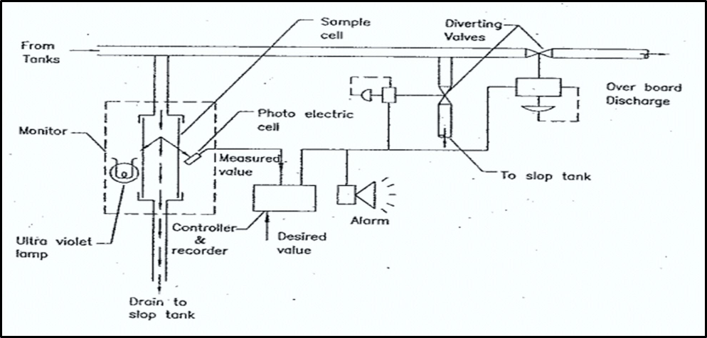
Operation:
- The principle used is that of UV fluorescence.
- UV light is absorbed and it is reflected back as longer wavelength.
- Oil fluoresces more readily than water and this provides the means for its detection.
- A sample is drawn off from the overboard discharge and passes through sample cell.
- An UV light is directed at the sample and fluorescence is monitored by a photoelectric cell.
- The measured value is compared with the maximum desired value in the controller/recorder.
- Where an excessive level of contamination is detected, an alarm is sounded and diverting valves are operated.
- The discharging liquid is then passed to a slop tank.
Functions:
- As per MARPOL Annex I Regulation 14,
Vessel of 10,000 GT and above shall be fitted with an oil filtering equipment that has
- Alarm function to indicate when the effluent has oil content of more than 15 ppm
- An arrangement to ensure that any discharge of oily mixtures is automatically stopped when the oil content of the effluent exceeds 15 ppm.
- Thus, an OCM provides2 an alarm to indicate when the oil content in the effluent is more than 15ppm and stops the discharge automatically.
Incinerator
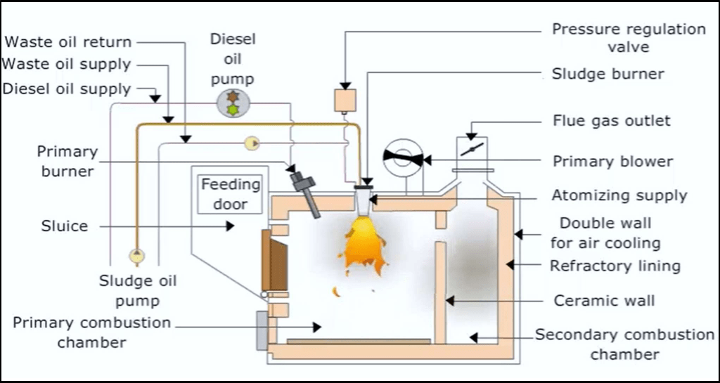
- The incineration is designed with a primary combustion chamber for burning sludge oil or solid waste.
- The secondary chamber is provided for burning out un-combusted exhaust gases.
- The primary combustion chamber is equipped with a primary burner.
- Diesel oil is supplied to this burner for initial ignition.
- After this, the sludge oil is supplied to the main burner until it ignites.
- The primary burner is then switched off either automatically or manually.
- Atomizing air is provided to the sludge burner for efficient combustion.
- A pressure regulating valve is provided on the sludge return line to adjust the quantity of sludge entering the combustion chamber.
- The heat from the primary burner will dry out and start burning the solid waste and or ignite the sludge oil.
- The very large heat transmission area in the primary combustion chamber optimizes the drying and burning of the solid waste.
- In the secondary combustion chamber, the gases from the primary combustion chamber will burn out.
- A wall made of ceramic, heavy duty refractory lining separates the primary and secondary chamber.
- In case of solid garbage or waste, the waste is put into the incinerator through the feeding door.
- Note that the primary burner cannot be ignited if this door is open.
- The rest of the combustion process is the same.
Items that cannot be burnt in an incinerator
- Shipboard incineration of the following substances shall be prohibited:
- residues of cargoes subject to Annex I, II or III or related contaminated packing materials;
- polychlorinated biphenyls (PCBs);
- garbage, as defined by Annex V, containing more than traces of heavy metals;
- refined petroleum products containing halogen compounds;
- sewage sludge and sludge oil either of which are not generated on board the ship;
- and exhaust gas cleaning system residues.
- Shipboard incineration of polyvinyl chlorides (PVCs) shall be prohibited, except in shipboard incinerator for which an IMO Type Approval Certificate have been issued.
- Shipboard incineration of sewage sludge and sludge oil generated during normal operation of a ship is permitted.
- Such incineration shall not take place inside ports, harbours and estuaries.
- Personnel responsible for the operation of an incinerator shall be trained.
- If incinerator is of the continuous-feed type, waste shall not be fed into the unit when the combustion chamber gas outlet temperature is below 850°C.
- If incinerator is of the batch-loaded type, the unit shall be designed so that the combustion chamber gas outlet temperature shall reach 600°C within five minutes after start-up and will thereafter stabilize at a temperature not less than 850°C