A cargo pump is a machine used to propel the liquid cargo from the tank into a pipe so that it may reach the shore tank (be discharged). We have learnt in our school days that the atmosphere can support a column of 10.336 m of fresh water (i.e. water of density 1.0000 kg/cm2). This means that if the open end of a pipe is immersed in a liquid and from the other end suction is created to generate a partial vacuum in the pipe. The liquid will start rising in the pipe and if it is water, it will rise to 10.336m and then stop. The level to which the liquid rises will depend of the density of the liquid. The liquid rises due to the atmospheric pressure acting on the surface of the liquid. Thus if the liquid is mercury, then the atmosphere can support 760 mm of mercury column. Stripping pumps use this principle to suck the cargo from the tank.
The various types of pumps commonly used on ships are;
- Centrifugal pumps
- Reciprocating pumps
- Screw type pumps
- Gear Pumps
- Eductors
Centrifugal pump
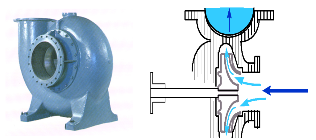
Principle: The centrifugal pump consists of one or more impellers mounted on a rotating shaft and enclosed in a casing. The liquid is fed to the centre of the impeller, and the impeller, which is rotating at a high speed, imparts its energy to the liquid, which is thrown outwards by centrifugal force and is collected in a volute where the kinetic energy is converted into pressure. In a centrifugal pump there are two sources of pressure; first is the pure centrifugal force and second is kinetic energy contained in the liquid. This pump is not capable of generating significant suction pressure and the liquid should be delivered to the suction side of the pump for the pump to perform satisfactorily.
Construction: The shaft of the pump may be vertically or horizontally mounted. The prime mover can be a diesel engine or a steam / gas turbine or an electric motor or hydraulic pressure. The shaft and the impeller(s) is / are enclosed in a casing. The size of the casing and the impellers will decide the capacity of the pump. The intermediate gear coupling between the prime mover and the pump should be inspected at intervals of 6 to 12 months and the grease inside should be replaced to avoid overheating.
Lift of the pump: The maximum difference between the level of the liquid from where the liquid is being transferred and the level of the liquid to where it is transferred is called the head of the pump. To understand this we need to understand the following definitions;
Suction lift: This is the height of the liquid above or below the centre of the pump. Thus if the level of the liquid is above the centre of the pump (as when commencing discharge), the suction head is positive and the suction pressure gauge will show 1 bar / 10 m head of the liquid above the centre of the pump. As the level falls in the tank, the suction head reduces until it becomes zero and then as the level of the liquid goes below the centre of the pump the suction head becomes negative. The negative suction head is measured in mmHg and it can reach 760 mmHg.
Actual pump head: The difference between the height of the liquid surface from where the liquid is being transferred and the height of the liquid surface to where the liquid is being transferred.
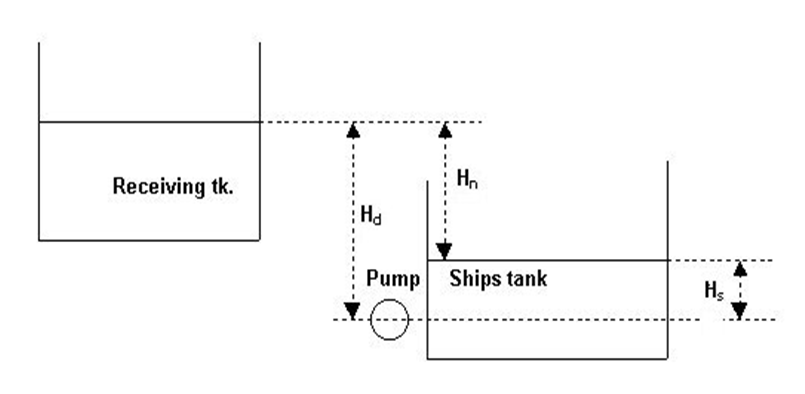
In the above figure, Hd is the height of the liquid in the receiving tank above the centre of the pump. Hn is the actual pump head. Hs is the suction head. Thus
Hd = Hn +Hs
There is a loss of head due to friction caused by the liquid flowing in the pipes. This will increase with the increase in the number of bends / valves/ other obstructions.
Precautions while starting a centrifugal pump:
Before starting the centrifugal pump it should be ascertained that there is no air in the suction line or the pump casing. All the valves on the suction side should be opened (This should be done very slowly so that the air in the line and the pump is vented to the discharge side. This should be followed more strictly if the pump suction pressure gauge is showing vacuum). The pump should be started against a closed discharge valve and as the pump RPM increases the discharge pressure also increases and when the discharge pressure is about 4 – 5 kg /cm2, the discharge valve is slowly opened. The discharge pressure is monitored and as the rpm is increased the discharge valve is also opened more till it is fully open. It should be ensured the pump is always full of liquid. It is possible that highly volatile cargo can cause “Gassing of the pumps”. This can be controlled by running the pump at low rpm and by applying external cooling to the pump casing. The impellers are likely to turn in the reverse direction if the cargo flows in the opposite direction through the pump. There is a non-return valve provided in the discharge side of the pump to prevent this from occurring.
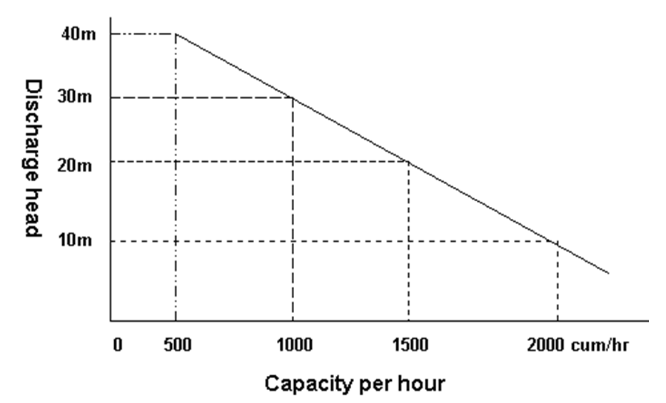
Ref to graph below for general characteristics (QH curve) of a centrifugal pump: .
Cavitation
Cavitation occurs due to the pump casing containing gas / air. This can be vented by opening the discharge side of the pump and opening a tank with high liquid head. The other means is by using a stripping pump or eductor to remove the air / gas from the casing. A primavac system may also be used for the same purpose.
Pressure surge
When a valve in a line where the liquid is being discharged at a constant rate is closed a pressure surge or water hammer effect is generated in the line. This is because the velocity is converted into pressure and this gives rise to pressure surge. This can also occur if, when there is a vacuum on one side of a valve and pressure on the other side, the valve is opened, the liquid is propelled at the speed of sound. The pressure generated is exceedingly large and is calculated by the formula;
P = (r x A x V) / g
Where P = Pressure in kg / cm2
r = Specific gravity
A = Speed of sound in the liquid
V = Speed of the flow of liquid in m / sec
g = Acceleration due to gravity
To prevent pressure surge, valves must be opened and closed slowly. In hydraulic valves the speed of valve operation is normally adjusted such that for every 20mm dia of a valve the time taken is 2 seconds. The table below gives the speeds for manual and hydraulic valves.
| Valve size (Dia in mm) | Time required to open / close fully |
| 200 – 250 mm | 10 – 15 seconds |
| 300 – 450 mm | 20 – 30 seconds |
| 500 – 700 mm | 40 – 50 seconds |
| 800 mm | 60 – 70 seconds |
Pressure surge can damage the valves, pipes and the pump casing.
Precautions to prevent pressure surge;
- If the suction gauge of the cargo pump is showing suction then the suction valve should be operated slowly.
- If there is a vacuum in the cargo pump then the pump should be operated after filling the line with cargo.
- When changing over tanks with the pump running, the pump revolutions should be brought to a minimum and the delivery valve should be adjusted accordingly.
Two cargo pumps operating in parallel
Cargo pumps are said to be running in parallel when they are discharging into the same line ashore.
If two pumps of the same characteristics are discharging into the same line then the pumps need to be monitored carefully. If the pump discharge pressures are not same, then the pump with the higher discharge pressure will continue to discharge while the pump with a lower discharge pressure will not be able to discharge cargo. The pump with lower discharge pressure will start to heat, as the velocity imparted to the cargo by the impellers will be converted into heat. This is a dangerous situation, which may lead to a fire.
Maintenance of a centrifugal pump
The centrifugal pump does not need too much attention and will give trouble free service provided the following is done:
- Before every operation of the pump the pump should be greased as per the instructions of the manufacturer. It should be appreciated that over greasing can lead to heating of the pump just as no greasing would.
- The ‘wear rings’ need to be replaced at regular intervals to get optimum performance from the pump.
- The pump should never be run dry.
- The strainers should be cleaned regularly.
Tips for ensuring trouble free operation of a centrifugal cargo pump
- The pump should be full of cargo before starting i.e. it should be primed before starting.
- Before starting the pump ensure that the discharge head (back pressure) is not more than the pumps rated discharge head.
- Regular maintenance to ensure that the impeller is clear.
- The pump to be started at idling RPM and once it is confirmed that all is OK on deck and pump room, the RPM should be increased as appropriate / required.
- Air should not be allowed to enter the suction side of the pump.
- Any vibration in the pump should be investigated immediately as it can lead to serious damage.
- The correct grade of grease as indicated in the manual should be used.
- The discharge valves may be manipulated but never the suction valves.
Vac-strip pump
A centrifugal pump, by itself, is not suitable for emptying a cargo tank since it is not a positive displacement pump. It will then start cavitating when some liquid is still left in the tank and eventually lose suction. For this reason one often finds a vac-strip system on ship. This consists of a separator tank in-line with the suction end of the main cargo pump. The vac-strip pump creates a vacuum in the main cargo pump as well as the separator tank which feeds the pump, thus creating an artificial positive cargo head.
The vac-strip pump consists of a rotating impeller which creates suction and draws out air/gas. A water sealing and cooling system is also provided for the pump.
Reciprocating pump
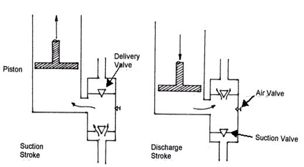
The reciprocating pump is so called because it has pistons, which have an up and down movement. It is a positive displacement pump and can discharge even gases and air and its efficiency is not affected by the ingress of gases into the pump. Since it is a positive displacement pump, the discharge valves should never be throttled. The pressure is regulated by controlling the number of strokes on the pump.
Note
It is a pump, which is used the least on a tanker but is damaged most often. This is so because the operation of the pump and the principles on which it works is not understood properly by most of the operators.
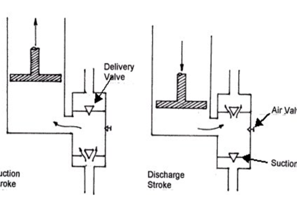
Principle of operation
The pump sucks in liquid in to the casing because the upward movement of the piston increases the internal volume of the chamber thereby creating a partial vacuum. The suction valve opens and the delivery valve closes thereby allowing liquid to enter into the suction chamber. On the downward stroke of the piston, the suction valve closes and the delivery valve opens and the liquid is forced out of the chamber into the discharge line.
Operation of a reciprocating pump
As steam is let in into the slide valve box, the steam pistons commence up – and – down motion as per the cycle of operation of the slide valves. The liquid pistons repeat the cycle of the steam pistons. When the liquid piston moves downwards, the pressure on the liquid opens the delivery valve and the liquid is discharged. At the same time the space above the piston is filled with liquid which has been sucked in through the suction valve. When the liquid piston goes up, the liquid above the piston is discharged and the liquid is sucked in into the space below the chamber. Thus the liquid is sucked into the space above and below the piston and is pushed into the discharge side of the pump.
Parts of a reciprocating pump
Slide valve box
It is a device, which supplies steam to the steam cylinder. It is fitted on one face of the cylinder. It has two liners, each of which have a steam port and an exhaust port. The slide valve is of the composite piston type and is provided with four piston rings. The slide valve while controlling the supply of steam to the cylinders repeats alternating up and down movements in the slide valve box.
Steam cylinder
The steam cylinders are cast in one block. The steam entering the cylinder moves the steam piston and this reciprocating movement of the steam piston is followed by the pump piston within the bucket and this creates a partial vacuum or suction in the pump cylinder. Thus the discharge capacity of the pump depends on the number of strokes per minute and the strokes are controlled by the steam flow (pressure).
Pump bucket
The pump piston alternately increases and decreases the volume of the space above and below the piston and this causes the liquid to be drawn in and pumped out of the bucket. We have seen that the bucket has inlet and outlet valves and they open and close as per the pressure difference in the bucket. If the pump is not operated properly, the pump bucket is liable to be damaged by the motion of the piston.
Group valve chest
The top and bottom valve chests are cast separately and connected together on both sides. The boxes are identical in construction, dimensions, and each has a suction valve chamber, a discharge valve chamber and suction chamber. The discharge valve consists of a seat, a disc, a valve spring, a steam and valve guard. It is fixed by pressing from the valve box cover by means of a jack bolt. The suction valve consists of a seat, a disc, a valve, a spring, a set bolt and a valve guard. It is fixed by pulling from the bottom by means of the set bolt.
Air vessel
As seen earlier, the reciprocating pump has a pulsating discharge as per the strokes of the piston. To make it a steady flow, an air vessel is inserted after the discharge valve. This is a sealed vessel and the air inside the vessel gets compressed by the cargo entering the vessel at the peak of the discharge stroke and when there is no discharge from the pump the air in the vessel expands and cargo is pushed out. This ensures a steady discharge.
Screw type pump
This pump consists of one or more screws (termed screws because of their surface profile). It consists of a central drive screw connected to the prime mover.
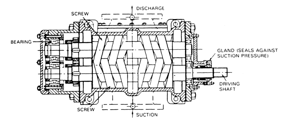
The other screw(s) known as idlers are meshed with the central drive screw. As the screws rotate, the liquid is pushed to the discharge side. The pump is self-priming and it does not set up vibrations or pulsations. These pumps are generally used to handle lubricating and other clean oils.
Gear pump
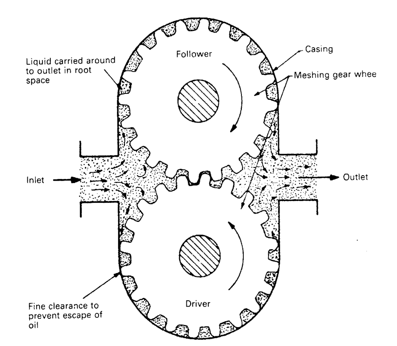
This is a positive displacement pump, which is very similar to a screw pump. It consists of 2 gears, which are meshed together within the body. As the gears rotate the liquid is trapped between the casing and the gear teeth. The liquid is forced out to the discharge side.
Eductors
These are also referred to as “Jet pumps”. There are no moving parts in the eductor and it operates on the “Venturi principle”. In the eductor the drive medium (liquid or gas) is delivered under pressure to the inlet of the eductor.
As the liquid passes through the nozzle there is an increase in velocity of the drive medium and this causes a pressure drop, which draws the liquid through the suction side of the eductor. The liquid drawn mixes with the drive liquid and this further increases the velocity of the liquid thus causing more efficient suction. After passing through the ‘throat’ the liquid passes into the diffuser where it regains its original velocity. If there is a backpressure at the discharge side of the eductor the efficiency of the eductor will reduce.
Eductors can be used to draw liquids and gases and since there are no moving parts it does not require any maintenance. It does not require monitoring as it cannot be damaged if air / gas is sucked in.
Its main disadvantage is that since it cannot discharge directly ashore, it increases the discharge time. If the drive pressure falls, then the drive liquid will start filling into the compartment. The capacity will depend on the drive pressure, suction lift and the discharge head.
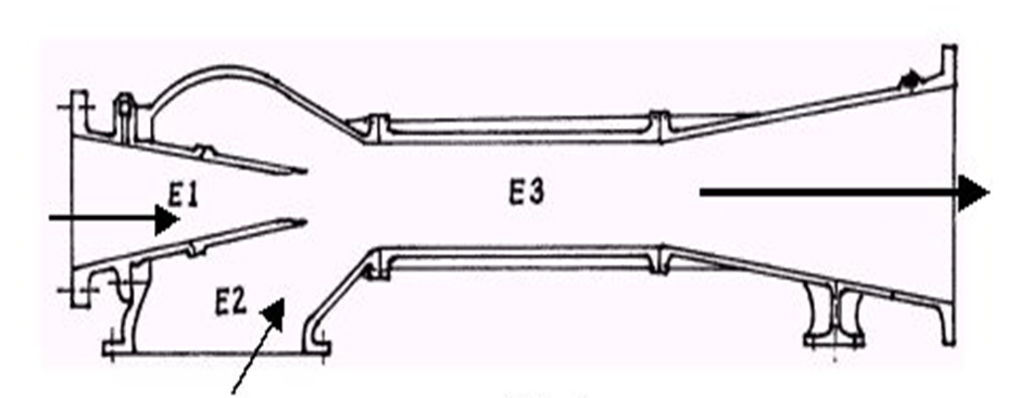
In above figure E1 is the inlet of the drive medium, E2 is the suction from the space to be educted and E3 is the discharge from the eductor.
The suction capacity depends on the relationship between suction lift and discharge head.
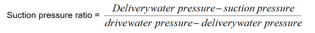
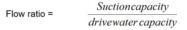
Any departure from the manufacturer’s specifications will result in an unfavorable ratio between the drive water capacity and the capacity of the educted liquid. Under favorable conditions these are equal. Thus if the suction valve is throttled to increase suction pressure, the suction capacity of the eductor will be reduced. The suction valve may be throttled to prevent air being drawn into the eductor.