What is Bilging
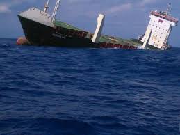
Bilging is said to occur when ingress of water takes place into the vessel from a point below the waterline, such that the water is free to flow in and out of the vessel. If the water enters the vessel from above the waterline then it will not be able to flow out of the vessel, in which case it is called flooding and not bilging.
Example

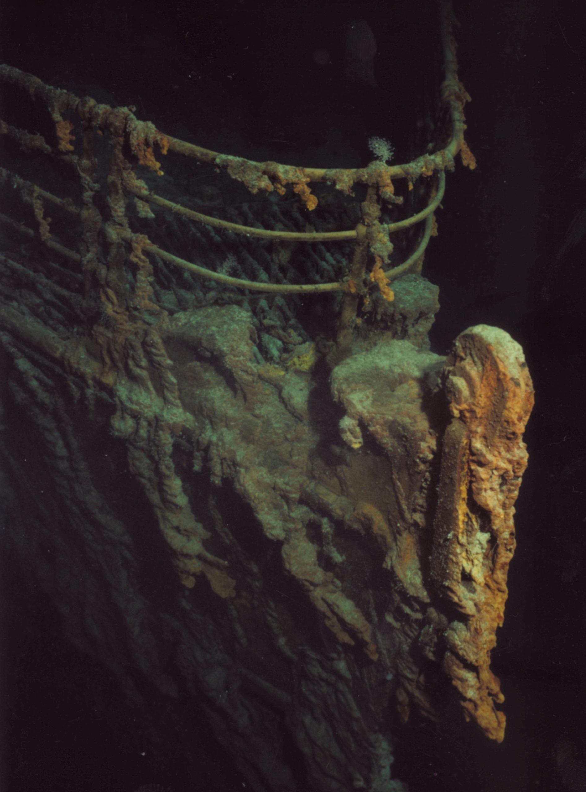
RMS Titanic was a British passenger liner that sank in the North Atlantic Ocean in the early hours of 15 April 1912, after colliding with an iceberg during her maiden voyage from Southampton to New York City.
THEORY
How stability is Affected
a) Bilging is said to occur when ingress of water takes place into the vessel from a point below the waterline, such that the water is free to flow in and out of the vessel. If the water enters the vessel from above the waterline then it will not be able to flow out of the vessel, in which case it is called flooding and not bilging.
b) After bilging, water level in the bilged compartment will be same as water level outside the vessel.
c) However, if the bilged compartment is a DB tank / deep tank, located at the bottom of the vessel, and it is fitted with a tank-top / watertight flat which is located below the outside water level, then water in the compartment will rise only upto the tank top / watertight flat.
d) Because the water is free to flow in and out of the bilged compartment, it is not part of the ship and hence there is no addition of weight i.e. the vessel’s displacement does not increase.
e) Because the displacement does not change, the COG of the vessel will not shift vertically, transversely or longitudinally from its original position i.e. the vessel’s KG and LCG will not change after bilging.
f) However, the part of the compartment, which is submerged under water, is lost to the sea i.e. the vessel’s underwater volume is said to be reduced by an amount equal to the volume of the bilged part of the compartment. Hence the vessel’s buoyancy is reduced.
g) To compensate for the lost buoyancy/volume without any change in displacement, the vessel will submerge till the same is regained so that once again the vessel’s buoyancy and displacement will remain equal.
h) This means that the vessel’s draft will increase due to bilging, but the underwater volume and the displacement of the vessel will not change.
i) Due to increase of the draft, COB of the vessel will shift upwards i.e. KB will increase.
j) Due to loosing and regaining of the vessel’s buoyancy, the shape of the vessel’s underwater volume will change. Hence the COB will also shift longitudinally and/or transversely, away from the bilged compartment.
k) Due to the longitudinal shift of COB, the horizontal distance between the new COB and the original COG will change, which will change the vessel’s trim.
l) Due to the transverse shift of COB, the horizontal distance between the new COB and the original COG will change, which will change the vessel’s list.
m) If the water level in the bilged compartment is the same as the water level outside the vessel, then the vessel’s water-plane is also said to be bilged i.e. the area of the water-plane is reduced by an amount equal to the area of the bilged compartment.
n) COF is the geometric centre of the water-plane. Hence, if the area of the water-plane is reduced due to bilging, then the COF will shift longitudinally and/or transversely, away from the bilged compartment.
o) Vessel’s water-plane will not reduce and its COF will not shift if the water level in the compartment does not rise upto the water level outside the vessel e.g. if a DB tank or a deep tank located at the bottom of the vessel is bilged.
p) Trim and list caused, as stated above, will occur about the new position of COF.
q) Loss of buoyancy/volume due to bilging will be less if the compartment has some solid cargo in it, because water entering the compartment will only occupy the empty spaces within the cargo i.e. the loss of buoyancy/volume will depend on the permeability of the compartment.
r) By the same theory, the loss of water-plane area due to bilging will also be less, depending on the permeability of the compartment.
s) Bilging of a part or full compartment does not affect the original FSM of the vessel, because the bilged compartment is not considered to be part of the vessel any more.
t) If a tank containing some liquid is bilged then it is assumed that initially the liquid in the tank is discharged, which will cause the following changes :
- Draft, U/W volume, displacement, KB and FSM will reduce.
- KG will increase.
- LCG, trim and list will change depending on location of the bilged tank.
- LCB will also change for vessel but for a box-shaped vessel it will remain the same as half the length of the vessel.
Subsequently, the empty tank is said to be bilged, which will further change the draft, KB, LCB, LCF, trim and list, as explained above.
CHANGES IN STABILITY PARAMETERS DUE TO BILGING
Following parameters will NOT change :
a) Displacement
b) Underwater volume
c) Position of COG i.e. KG, LCG and distance of COG from shipside
d) Shape and size of water-plane, when the level of water in the bilged tank/compartment is less than the level of water outside the ship
e) Position of COF i.e. LCF and distance of COF from shipside, when the shape and size of water-plane does not change
f) FSM / FSC
Following parameters will change :
a) Hydrostatic draft will increase
b) Position of COB i.e. KB, LCB and distance of COB from shipside
c) Trim and List
d) Shape and size of water-plane will reduce, when the level of water in the bilged compartment is same as the level of water outside the ship.
e) Position of COF i.e. LCF and distance of COF from shipside, when the shape and size of water-plane changes
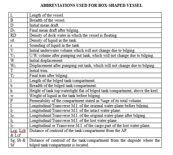
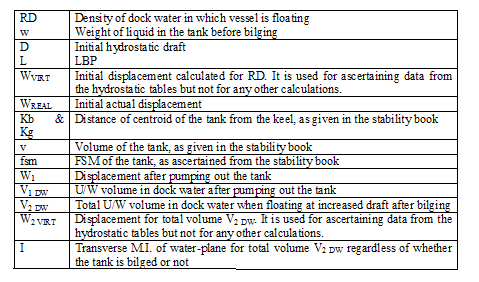
ABBREVIATIONS USED FOR BOX SHAPED VESSEL
CALCULATION OF MEAN DRAFT (D1) AFTER BILGING OF TANK/ COMPARTMENT REGARDLESS OF ITS LOCATION
STEP 1 — Calculate U/W volume (V1) after pumping out the tank.
V = L x B x D ; W = V x RD ; w = l x b x s x rd ; W1 = W – w ; V1 = W1 ÷ RD
STEP 2 — Calculate permeability (P %) of the compartment.
BS = SFC – (1 ÷ RDC) ; P = (BS ÷ SFC) ´ 100
BS — Broken stowage ; SFC — Stowage factor of the cargo ; RDC — Relative density of cargo
STEP 3 — Calculate mean draft (D1) after bilging.
CASE 1 — Compartment extends from bottom upwards without any watertight flat.
V1 = (L × B × D1) – (l × b × D1 × P ÷ 100)
CASE 2 — Compartment fitted with a watertight flat below the waterline, and bilging occurs only below this flat e.g. D.B. tank.
V1 = (L × B × D1) – (l × b × h)
CASE 3 — Compartment fitted with a watertight flat below the waterline, and bilging occurs only above this flat e.g. above D.B. tank.
V1 = (L × B × D1) – { l × b × (D1 – h) × P ÷100 }
CASE 4 — Compartment fitted with a watertight flat below the waterline, and bilging occurs both above and below this flat.
V1 = (L × B × D1) – { l × b × (D1 – h) × P ÷ 100 } – (l × b × h)
CALCULATION OF GM(F) AFTER BILGING
STEP 1 — Calculate KG1 after pumping out the tank. (It will remain same after bilging)
KG1 = { (W x KG) – (w x s ÷ 2) } ÷ W1
STEP 2 — Calculate FSM1 after pumping out the tank. (It will remain same after bilging)
I (tank) = l x b3 ÷ 12 ;
fsm (tank) = I (tank) × rd ; FSM1 = FSM – fsm (tank)
STEP 3 — Calculate mean draft (D1) after bilging, as explained above.
STEP 4 — Calculate position of COF1 after bilging of a side compartment, measured from the shipside where the compartment is located (SF1).
CASES 1, 3 & 4 — SF1 = { (L × B × B/2) – (l × b × Sf x P ÷ 100) } ÷ { (L × B) – (l × b × P ÷ 100) }
Note : For Case 1, SF1 = SB1
CASE 2 — COF does not shift because the W/P remains intact even after bilging.
Hence SF1 = SF = B/2
STEP 5 — Calculate transverse M.I. of the intact water-plane (II) about the longitudinal axis passing through the COF1.
CASES 1, 3 & 4 —
IO = (L × B3 ÷ 12) + { L × B × (SF1 – B/2)2 }
IL = (l × b3 ÷ 12) + { l × b × (SF1 – Sf)2 }
IC = { (l × b3 ÷ 12) × (100 – P)2 ÷ 1002 } + { l × b × (SF1 – Sf)2 × (100 – P) ÷ 100 }
II = IO – IL + IC
CASE 2 — There is no change in the water-plane hence II = I
STEP 6 — Calculate KB1 after bilging.
CASE 1 — KB1 = D1 ÷ 2
CASE 2 — KB1 = { (L × B × D1 × D1 ÷ 2) – (l × b × h × h ÷ 2) } ÷ V1
CASE 3 — KB1 = [ (L × B × D1 × D1 ÷ 2) – { l × b × (D1 – h) × [{(D1 – h) ÷ 2}+ h] × P ÷ 100 } ] ÷ V1
CASE 4 —KB1 = [ (L×B×D1×D1÷2) – (l×b×h×h/2) – { l×b×(D1 – h)×[{(D1 – h)÷2}+ h]×P÷100 } ] ÷ V1
STEP 7 — Calculate G1M(F).
B1MT = II ÷ V1 ; KMT = KB1 + B1MT ; G1M(F) = KMT – KG1 – (FSM1 ÷ W1)
CALCULATION OF FORWARD AND AFT DRAFTS AFTER BILGING OF TANK/ COMPARTMENT LOCATED ANYWHERE ALONG THE LENGTH OF VESSEL
STEP 1 — Calculate initial LCG.
I = B × L3 ÷ 12 ; BML = I ÷ V ; MCTC = (W × BML) ÷ (100 × L)
BG = T × MCTC ÷ W ; LCB = L ÷ 2
LCG = LCB ± BG ; Trim aft : -ve ; Trim ford. : +ve ; Trim zero : BG = 0
STEP 2 — Calculate LCG1 after pumping out the tank. (It will remain same after bilging)
LCG1 = { (W x LCG) – (w x Lcg) } ÷ W1
STEP 3 — Calculate mean draft (D1) after bilging, as explained above.
STEP 4 — Calculate LCB1 after bilging.
CASE 1 — LCB1 = { (L × B × D1 × L/2) – (l × b × D1 × Lcb × P ÷ 100) } ÷ V1
CASE 2 — LCB1 = { (L × B × D1 × L/2) – (l × b × h × Lcb) } ÷ V1
CASE 3 — LCB1 = [ (L × B × D1 × L/2) – { l × b × (D1 – h) × Lcb × P ÷ 100 } ] ÷ V1
CASE 4 —LCB1 = [ (L × B × D1 × L/2) – (l × b × h × Lcb) – { l × b × (D1 – h) × Lcb × P ÷100 } ] ÷ V1
STEP 5 — Calculate LCF1 after bilging.
CASES 1, 3 & 4 —
LCF1 = { (L × B × L/2) – (l × b × Lcf ´ P ÷ 100) } ÷ { (L × B) – (l × b × P ÷ 100) }
Note : For Case I, LCF1 = LCB1
CASE 2 — COF does not shift because the W/P remains intact even after bilging.
Hence LCF1 = LCF = L / 2
STEP 6 — Calculate longitudinal M.I. of the intact water-plane (II) about the transverse axis passing through the COF1.
CASES 1, 3 & 4 —
IO = (B × L3 ÷ 12) + { L × B × (LCF1 ~ L/2) 2 }
IL = (b × l3 ÷ 12) + { l × b × (LCF1 ~ Lcf)2 }
IC = { (b × l3 ÷ 12)´(100 – P)2 ÷ 1002 } + { l × b × (LCF1 ~ Lcf)2 × (100 – P) ÷ 100 }
II = IO – IL + IC
CASE 2 — There is no change in the water-plane hence II = I
STEP 7 — Calculate final trim (T1) and forward and aft drafts.
B1ML = II ÷ V1 ; MCTC1 = (W1 × B1ML) ÷ (100 × L) ; B1G1 = LCB1 ~ LCG1
T1 = W1 × B1G1 ÷ MCTC1
LCB1 > LCG1 — Trim aft ; LCB1 < LCG1 — Trim ford.
TA = T1 × LCF1 ÷ L ; TF = T1 – TA
Trim aft — F = D1 – TF ; A = D1 + TA
Trim ford. — F = D1 + TF ; A = D1 – TA
CALCULATION OF LIST AFTER BILGING OF TANK/COMPARTMENT LOCATED ANYWHERE ON ONE SIDE OF THE CENTRELINE
STEP 1 — Calculate position of COG1, off centreline, if vessel already has a list (q). (It will not shift after bilging, unless STEP 2 is applicable)
KB = D ÷ 2 ; I = L × B3 ÷ 12 ; BMT = I ÷ V ; KMT = KB + BMT
GM(F) = KMT – KG – (FSM ÷ W) ; GG1 = GM(F) × Tan q
STEP 2 — Calculate position of COG2 after pumping out the tank, measured from the shipside where the tank is located (SG2). (It will not shift after bilging)
SG1 & SG2 — Distances of COG1 and COG2 respectively, from the shipside where the tank is located.
SG2 = { (W x SG1) – (w x Sg) } ÷ W1
STEP 3 — Calculate KG2 after pumping out the tank, as explained above. (It will remain the same after bilging)
STEP 4 — Calculate FSM1 after pumping out the tank, as explained above. (It will remain the same after bilging)
STEP 5 — Calculate mean draft (D1) after bilging, as explained above.
STEP 6 — Calculate position of COF1 after bilging of a side compartment, measured from the shipside where the compartment is located (SF1), as explained above.
STEP 7 — Calculate transverse M.I. of the intact water-plane (II) about the longitudinal axis passing through the COF1, as explained above.
STEP 8 — Calculate KB1 after bilging, as explained above.
STEP 9 — Calculate G2M(F), as explained above.
STEP 10 — Calculate position of COB1 after bilging of a side compartment, measured from the shipside where the compartment is located (SB1).
CASE 1 — SB1 = { (L × B × D1 × B/2) – (l × b × D1 × Sb x P ÷ 100) } ÷ V1
Note : For this Case, SF1 = SB1
CASE 2 — SB1 = { (L × B × D1 × B/2) – (l × b × h × Sb) } ÷ V1
CASE 3 — SB1 = [ (L × B × D1 × B/2) – { l × b × (D1 – h) × Sb x P ÷100 } ] ÷ V1
CASE 4 — SB1 = [ (L × B × D1 × B/2) – { l × b × (D1 – h) × Sb x P ÷ 100 }– (l × b × h × Sb) ] ÷ V1
STEP 11 — Calculate final list (q1).
B1G2 = SB1 ~ SG2 ; Tan q1 = B1G2 ÷ G2M(F)
If SB1 > SG2, list will be towards the side of the bilged compartment.
If SB1 < SG2, list will be opposite to the side of the bilged compartment.
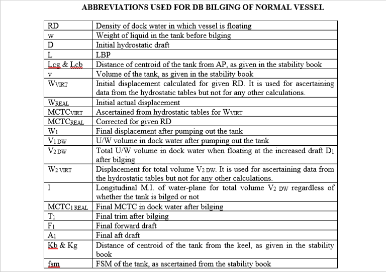
CALCULATION OF FORWARD AND AFT DRAFTS AFTER BILGING OF VESSEL D.B. TANK
STEP 1 — Calculate initial LCG.
CASE 1
Data given — F (ford. draft) , A (aft draft) , RD , Tank bilged , w
Calculate — T (trim) , Mean draft , LCF (for mean draft)
D = A ± {(T × LCF) ÷ L} ; Trim aft : -ve ; Trim ford. : +ve
Ascertain — WVIRT , MCTCVIRT , LCB , Lcb = Lcg , v
Calculate — WREAL = WVIRT × RD ÷ 1.025 ; MCTCREAL = MCTCVIRT × RD ÷ 1.025
BG = T × MCTCREAL ÷ WREAL
LCG = LCB ± BG ; Trim aft : -ve ; Trim ford. : +ve
CASE 2
Data given — W , LCG , RD , Tank bilged , w
Ascertain — Lcb = Lcg , v
CASE 3
Data given — W , T(trim) , RD , Tank bilged , w
Calculate — WVIRT = WREAL ×1.025 ÷ RD
Ascertain — MCTCVIRT , LCB , Lcb = Lcg , v
Calculate — MCTCREAL = MCTCVIRT × RD ÷ 1.025 ;
BG = T × MCTCREAL ÷ WREAL
LCG = LCB ± BG ; Trim aft : -ve ; Trim ford. : +ve
STEP 2 —Calculate U/W volume (V1 DW) in dock water after pumping out the tank.
W1 REAL = WREAL – w ;
W1 VIRT = W1 REAL × 1.025 ÷ RD ;
V1 DW = W1 VIRT ÷ RD
STEP 3 — Calculate LCG1 after pumping out the tank.
LCG1 = { (WREAL × LCG) – (w × Lcg) } ÷ W1 REAL
STEP 4 — Calculate LCB2 after bilging.
V2 DW = V1 DW + v ; W2 VIRT = V2 DW × RD
Ascertain — D1 , LCB1 , LCF1 , KB , KML
LCB2 = { (V2 DW × LCB1) – (v × Lcb) } ÷ V1 DW
STEP 5 — Calculate ford. and aft drafts after bilging.
B2G1 = LCB2 ~ LCG1 ; BML = KML – KB ; I = BML × V2 DW ; BML1 = I × V1 DW
MCTC1 REAL = (W1 REAL × BML1) ÷ (100 × L)
T1 = W1 REAL × B2G1 ÷ MCTC1 REAL
LCB2 > LCG1 : Trim aft ; LCB2 < LCG1 : Trim ford.
TA = T1 × LCF1 ÷ L ; TF = T1 – TA
Trim aft : F1 = D1 – TF ; A1 = D1 + TA ; Trim ford. : F1 = D1 + TF ; A1 = D1 – TA
CALCULATION OF GM(F) AFTER BILGING OF VESSEL D.B. TANK
STEP 1 — Calculate initial data.
CASE 1
Data given — F(ford. draft) , A(aft draft) , RD , KG , FSM , Tank bilged , w
Calculate — T(trim) , Mean draft , LCF(for mean draft)
D = A ± {(T × LCF) ÷ L} ; Trim aft : -ve ; Trim ford. : +ve
Ascertain — WVIRT , Kg = Kb , v , fsm
Calculate — WREAL = WVIRT × RD ÷ 1.025
CASE 2
Data given — W , KG , FSM , RD , Tank bilged , w
Ascertain — Kb = Kg , v , fsm
STEP 2 — Calculate U/W volume (V1 DW) in dock water after pumping out the tank.
W1 REAL = WREAL – w ;
W1 VIRT = W1 REAL × 1.025 ÷ RD ;
V1 DW = W1 VIRT ÷ RD
STEP 3 — Calculate KG1 after pumping out the tank.
KG1 = { (WREAL × KG) – (w × Kg) } ÷ W1 REAL
STEP 4 — Calculate FSC after pumping out the tank.
FSM1 = FSM – fsm ; FSC = FSM1 ÷ W1 REAL
STEP 5 — Calculate KB1 after bilging.
V2 DW = V1 DW + v ; W2 VIRT = V2 DW × RD
Ascertain — KB , KMT
KB1 = { (V2 DW × KB) – (v × Kb) } ÷ V1 DW
STEP 6 — Calculate G1M1(F).
BMT = KMT – KB ; I = BMT × V2 DW ; BMT 1 = I × V1 DW ;
KMT 1 = KB1 + BMT 1
G1M1(S) = KMT 1 – KG1 ; G1M1(F) = G1M1(S) – FSC