Purpose of boiler on ships? Steam Generation:
- The primary purpose of a boiler is to generate steam.
- Steam is used for various applications on board ships, including propulsion, power generation, heating, and operation of auxiliary machinery.
Propulsion:
- The steam generated by the boiler powers steam turbines or engines, providing the necessary thrust for propulsion.
- This is particularly common in steam-powered vessels.
Power Generation:
- The boiler produces steam to drive steam turbines or generators, converting thermal energy into electrical power for the ship’s electrical systems and equipment.
Heating:
- Steam from the boiler is utilized for heating purposes on board, such as providing hot water for domestic use, heating fuel oil, or maintaining suitable temperatures in cargo tanks or living quarters.
Cargo Operations:
- Some specialized vessels use boilers for specific cargo operations, such as tankers with boiler heating systems to heat and maintain the viscosity of cargo, such as heavy fuel oil or chemicals.
Auxiliary Machinery:
- The boiler provides steam to power various auxiliary machinery and systems on board, including pumps, compressors, winches, and other equipment necessary for ship operations.
How circulation of water takes place in such boiler
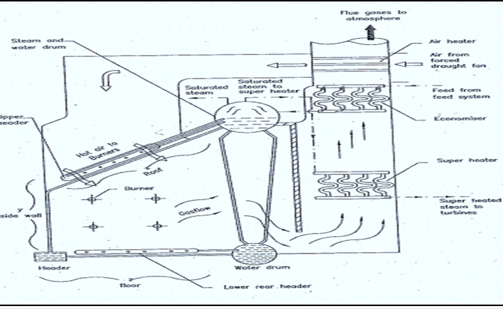
- Also known as foster wheeler ESD type water tube boiler.
- This consists of two horizontal cylindrical drums, one above the other. The top being the steam drum and bottom the water drum.
- These are connected directly by vertical generating tubes and other tubes via headers.
- Burner provides the necessary heat. And baffles are fitted to direct the hot gasses from all burners.
- The feed water circulates from the steam drum to the water drum and is heated in the process.
- The steam is produced in the steam drum and enters to the inlet of super heater.
- This steam is further heated and dried in the super heater and leaves through the outlet.
- The attemperatori.e. a steam cooler maybe fitted in the system to control the super heated steam temperature.
- Before water enters the economizer, it gets heated by the hot gasses from the furnace thereby increasing the efficiency.
- The economizer is so called because economy is affected by transferring heat from the hot waste gases to the boiler feed water. This heat which would otherwise be lost in the gases escaping up the funnel, increases the temperature of the feed water, hence less heat is required from the fuel.
- The whole system is encased in sheet steel with fire brick work bolted to inside and thermal lagging to outside of casing.
Smoke tube aux. boiler
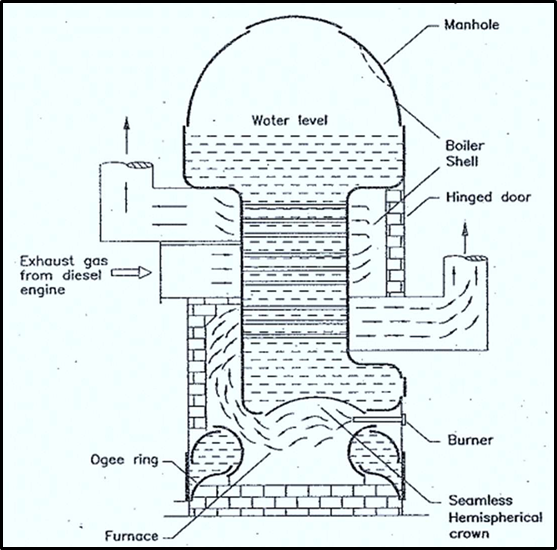
- Also known as Cochran smoke tube boiler or fire tube boiler.
- Suitable for producing relatively small amount of low-pressure steam for auxiliary purposes.
- The fuel is burn in the furnace having hemispherical crown.
- The crown is attached to the boiler shell by means of an ogee ring.
- The hot gases pass from fire through one or more tubes.
- Thus, water which is in contact with the tubes gets heated by thermal conduction.
- This above figure is of a composite boiler which means the steam can be generated using heat either from main engine exhaust gas or from oil firing or from both. Thus, it is also called as exhaust gas boiler.
- When the vessel is in port the generation of steam can be maintained by oil firing.
- Internal access to the boiler is provided by a manhole in the top of the shell, while handholes in the lower section of the shell provides access to the lower part of the water space for cleaning and inspection.
Important mountings of a boiler stating their use.
- Water gauge.
- Safety valve
- Main steam stop valve.
- Auxiliary stop valve
- Main feed check valve
- Blow down valve
- Air vent
- Salinometer valve
- Pressure gauge cock
- Soot blowers
Water Gauge:
- The water gauge is a glass tube gripped in steam tight glands with steam and water cocks.
- The water level in the boiler can be seen as it takes up same level in the glass.
Safety Valve:
- The safety valve is provided to prevent over pressure.
- Minimum of two safety valves to each boiler is fitted.
- The safety valve fitted with had operated easing gear by which the valves can be manually floated in case of emergency.
Main Steam Stop Valve:
- Function is to isolate the boiler from the main steam line. Its fitted on top of the boiler on main steam line.
- It is either full open when boiler is supplying steam to the main turbines or closed tight when boiler is not supplying main steam.
- Usually SDNR type to prevent steam flowing back in to the boiler.
Auxiliary Stop Valve:
- Function is to isolate the boiler from auxiliary steam lines.
- Auxiliary steam line carries steam to various steam to various steam pumps, winches heaters etc.
- Usually SDNR type to prevent steam flowing back in to the boiler.
Main Feed Check Valve:
- Fitted to provide final control over the entry of feed water into the boiler.
- Positioned on the shell of the boiler at the water level.
- Usually SDNR type so that in the event of a loss of feed pressure, to prevent boiler water blow back into the feed line.
Blow Down Valve:
- These are fitted to the water drum to enable water to be blown from the boiler in order to reduce the density.
- Consists of two valves mounted in series. First valve must be full open before the second can be cracked open i.e. sufficient to give the required rate of blow down.
Air Vents:
- These are fitted to the upper parts of the boiler as required to release air from drums and header.
- Air is released first while filling the boiler with water and later while raising steam to let the inside air out.
- Also lets in air when boiler is cooling off during shutdown.
Salinometer Valve:
- These are fitted to the water drum to enable samples of boiler water to be drawn off so that the boiler water tests required for the control of the feed water treatment can be carried out.
Pressure Gauge Cock:
- This is provided on the steam space.
- To this cock is connected a pipe up to steam pressure gauge placed at a convenient place at eye level.
Soot Blowers:
- Operated by steam or compressed air, they act to blow away soot and products of combustion from the tube surfaces.
- Several blowers are placed at strategic places.
Procedure for raising steam in a boiler from cold
- Fill boiler with water to about one-quarter of the water level gauge glass. Make sure the air vent is open.
- Make sure no oil lying in the bottom of the furnace before lighting up.
- Run the forced draught fan and purge the furnace.
- Line up all the valves and start the fuel booster pump, checking to see that enough oil is there in the service tank.
- Open the air to furnace. When the thermometer on the boiler front indicates correct temperature of the oil, put the lighted torch into the furnace and open oil to one of the burners at the lowest possible rate.
- Fire the boiler at short intervals, for very small periods, to enable it to warm up gradually. Failure to do so could lead to thermal stresses.
- When steam start coming out of the air vent, shut the vent and slowly raise steam to the proper working pressure.
- Following must be checked:
- Test water gauge by blowing through
- check boiler pressure gauge
- check boiler safety valve,
- check easing gear whether it’s clear.
- Firing rate may now be increased if all the checks are found satisfactory.
- Boiler is ready to supply required steam.
Difference between water tube and fire tube boiler
| Aspect | Water Tube Boiler | Smoke Tube Boiler |
| Operating Principle | Water circulates inside the tubes, which are exposed to the hot gases from the furnace. | Hot gases flow through the tubes, while water surrounds the tubes in the shell. |
| Heat Transfer Method | Convection and radiation heat transfer. | Mostly radiation heat transfer. |
| Steam Production | Generates high-pressure steam. | Typically produces low-pressure steam. |
| Size and Capacity | Generally used for large capacity applications. | Suitable for small to medium capacity applications. |
| Pressure Handling | Handles higher pressure levels | Limited to low to medium pressure applications. |
| Efficiency | Generally higher efficiency due to higher surface area for heat transfer. | Lower efficiency due to less heat transfer surface area. |
| Water Requirement | Requires a larger volume of water | Requires a smaller volume of water. |
| Response to Load Changes | Slower response time to load changes | Faster response time to load changes. |
| Safety | Safer due to better water circulation and higher-pressure handling capability. | Slightly less safe due to potential tube rupture. |
| Maintenance | More complex and requires skilled labour. | Relatively simpler and less labour- intensive. |
Boiler safety valves and at what pressure are boiler safety valves set
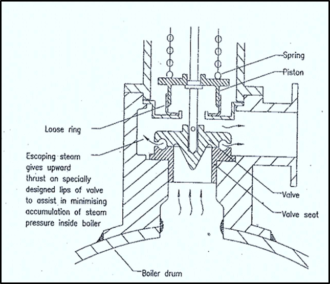
- This is a Safety device fitted to the boiler to prevent overpressure.
- Minimum of two safety valves to each boiler must be fitted.
- The valves are required to be: –
- Set to blow off at a pressure not exceeding 3% of the working pressure.
- It must me designed so that, under full firing conditions of the boiler and with the steam stop valve shut the valve must lift sufficiently so that the pressure does not rise above 10% of designed blow-off pressure i.e. valve should not allow steam to accumulate.
- It is also called accumulation test of the boiler.
- Specially shaped lips on the valve and seat assist in minimising accumulation of steam pressure.
- Waste steam piston also helps to give further increased valve lift.