When a ship has to steer a single course for a long time it would be tiresome for the helmsman to concentrate and steer. The aytopilot does the job of the helmsman by continuously obtaining feedback from the gyrocompass and commanding the steering gear approporately such that the ship steers the course set by the officer of the watch (OOW).
This not only relieves the helmsman from steering duties but is also more efficient. As soon as the ship deviates from the set course, corrective action is immediately taken using requisite amount of helm to bring the ship back to the set course.
This is achieved by comparing the course set by the OOW with the Gyro compass heading of the ship, any difference between the two will cause an error and correcting helm is applied to the rudder.
Autopilot functioning:-
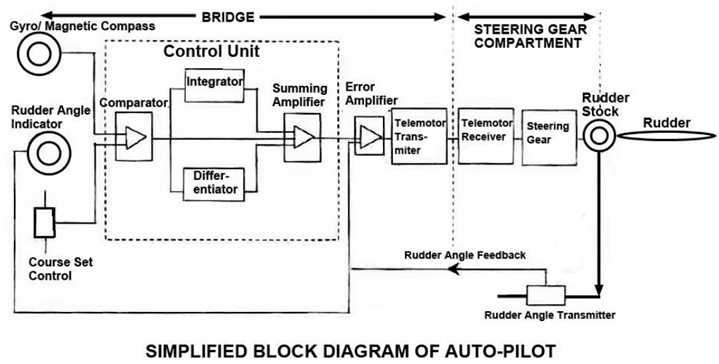
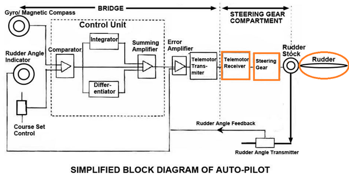
The course to be steered is selected by the course setting control knob while the present heading of the ship is indicated on the gyro or the magnetic compass.
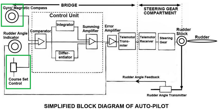
The output from gyro/ magnetic compass is coupled to the comparator in the control unit along with the input signal from manual course setting control.
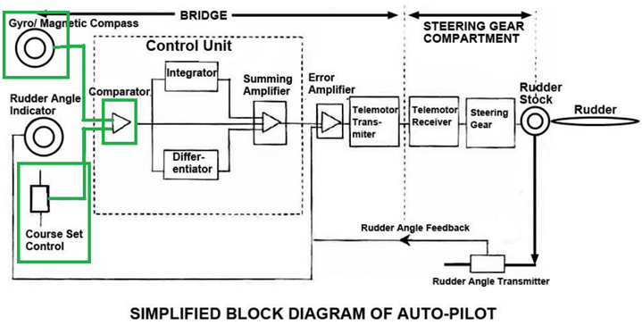
Any difference between the compass signal and course setting signal causes an output error signal whose magnitude is proportional to the difference between the two signals and hence the comparator is also referred to as proportional control.
In addition to the proportional control, the control unit also consists of derivative (differentiator) and integral (integrator) controls, which analyses the signals from the gyro or magnetic compass and the course setting control.
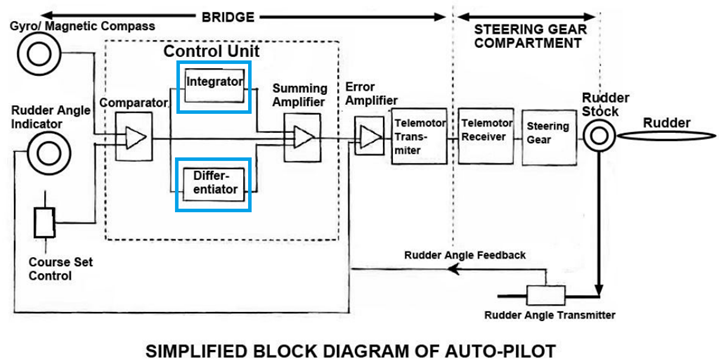
A summing amplifier is used to obtain a resultant signal from these three controls (Proportional, integral and derivative)
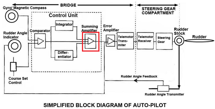
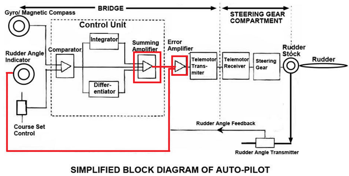
The resultant signal from summing amplifier is fed to the error amplifier, which also gets feedback signals from the rudder angle indicator.

The output of the error amplifier (error signal) is fed via telemotor transmitter on the bridge to the telemotor receiver in steering gear compartment.
Telemotor receiver controls the steering gear and in turn rotates the rudder stock and the rudder.
There will be not output from the comparator when the difference between compass and course setting signal is zero. Then the output from summing amplifier will also be zero, and hence no movement of the rudder results. Under this condition ship is on course
The Autopilot controller generally uses three types of control to keep the ship on track and steer the set course. These are:
Proportional Control:
In proportional control helm is applied by an amount proportional to the offcourse error.
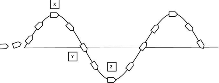
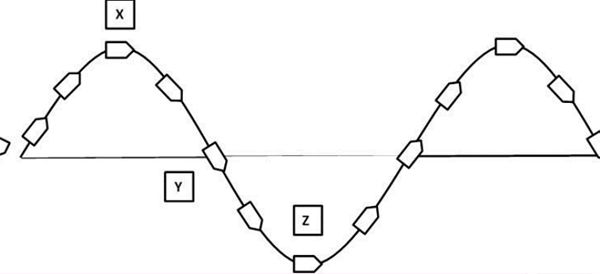
As per above figure, when the ship has gone offcourse to port from the set course, corrective starboard helm is applied in proportion to the off-course.
As th off-course increases, the corrective helm is also increased, Maximum starboard helm will then be applied at a point “X” to starboard.
When the ship starts returning to the track the offcourse reduces and hence the corrective helm is also reduced.At point “Y” since the offcourse is nil the corrective helm is zero.
But the ship continues to alter to starboard due to the turning momentum gained from “X” to “Y”
Once on the starboard side of the trach “Z” the suopilot applies corrective helm to the port side proportionate to the off-course.
This goes on and as a result the ship sails on a zig-zag track, if only proportional control is applied. This is also known as hunting along the set course.
Integral Control:
Due to certain design errors of a ship, when the helm is put on amidships the ships tends to move towards port or starboard while making headway.
Signals produced by continuously sensing this heading error over a period of time are added up and used to determine an appropriate degree of permanent helm required to keep the ship on a steady course.
The zero position of the helm therefore shifts to a new position, equal to the permanent helm. This is more a resetting action that brings the offset to zero eventually.
Derivative Control
In Derivative control the amount of helm applies is proportional to the rate of change of ship’s deviation from the course.
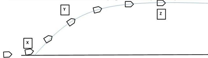
A deviation of course to port at “X” will result in corrective helm to starboard. The corrective helm proportional to the rate of change of course will reach maximum at “Y” where the rate is the highest.
The rate of change of course decreases due to applied corrective helm. This results in reduction in the corrective helm as well. At “Z” the rate of change of course is nil hence the rudder returns to midship.
The ship now steers the same course but is on a track parallel to the original track.
Derivative control is more like a damping force and helps the ship to settle down faster.
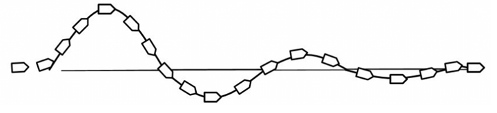
P& D Control
A controlled combination of proportional and derivative control produces a satisfactory return to course as shown in the below figure.
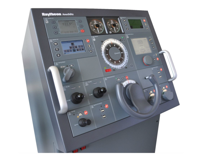
Controls fitted on steering console and their purposes:
Course selector knob
It is used to set the course to be steered.
Permanent Helm
This control is used when the ship is driven off course by cross winds
Rudder control
Set the number of degrees of rudder per degree of course error. The higher the setting, the larger the rudder angle used to correct a course deviation and this may result in over correcting. On the contrary on a low setting, less rudder angle is used to correct a course deviation and the ship will take a long time to return to the set course.
Speed
The speed of the ship determines the effectiveness of the rudder. The lower the speed less effective is th e rudder and vice versa. On modern ships this is arranged by taking a feed from the ships speed log or even the GPS.
Hydraulic pumps
Switch to run hydraulic pumps 1 or 2 or both
Counter Rudder
This determines the amount of counter action by the rudder to be used to steady the ship on the set course keeping the overshoot to a minimum.
Rudder limit
This control specifies the maximum degree of rudder the Auto Pilot is allowed to use for correcting or for counteracting. This is set by the navigator to suit the requirements related to sea-room, traffic condition, loading condition of the ship and weather conditions.
Telemotor
Switch to run telemotor 1 or 2.
Yaw
The setting of the yaw control depends on the wind and weather condition and their effect on the course keeping ability of the ship. In bad weather with strong winds higher value to be set while in fair weather low value is preferred.
Mode selector switch
The control is used to set the mode of steering between hand steering, auto-pilot and non-follow up steering.
Offcourse Alarm
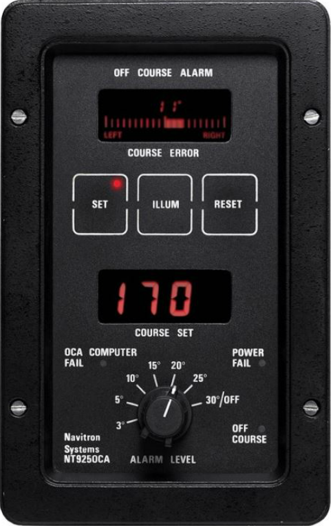
This alarm is activated if the ship deviates from the set course by a pre-decided limit.
This limit is set by the Navigator as per the instructions of the Master.
The limit can be different for different weather conditions, traffic density and loading condition of the ship.
This alarm also serves as a warning in case the autopilot fails and the ship deviates from the set by the limit fed in.
Different modes of steering; Follow-up and Non-Follow up
The hierarchy charts shows the different modes of steering.
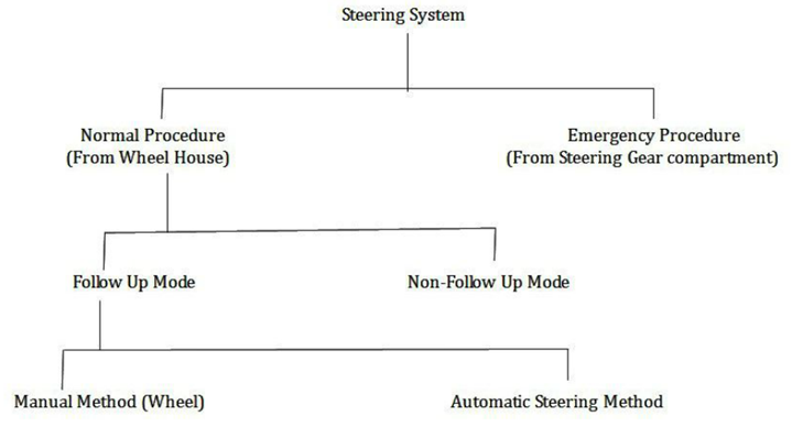
Follow up (FU) Mode:
As the name goes a follow up or feedback is received to the bridge steering control from the steering mechanism about the rudder position and movement. This is the principal mode of steering on vessels.
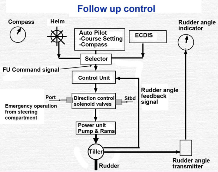
In this mode, the rudder follows the helm. If the rudder is put 10° to starboard the rudder will follow to 10° to stbd and remain there as long as wheel is kept to 10° to stbd.
To bring the rudder to amidships the helm will have to be brought to amidships.
This mode is followed in the following methods of steering:-
- The hand steering mode in which the steering wheel sets the rudder angle.
- Auto pilot steering mode in which the helm order is automatically generated depending upon the difference between the ordered course and the actual course.
Non- Follow up (NFU) Mode
This mode of steering is not done with a steering wheel but with a NFU lever.
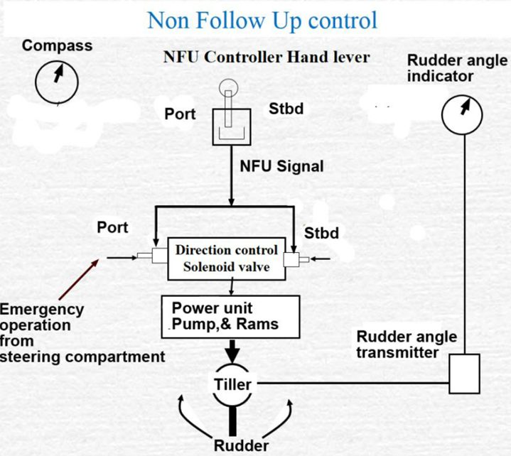
The NFU lever does not have any markings. As long as it is kept pressed, the rudder will continue turning and stop the moment the lever is released.
This mode is used when ships telemotor system fails. In that case, the NFU lever sends rudder setting directly to the direction control solenoid valves.
To return the rudder to the amidships, the NFU lever will have to be pressed to the opposite side of the initial movement and kept pressed till the rudder is amidships,
This mode involves one-way communication and there is no scope of receiving feedback from the steering machinery to the bridge control.
Procedure for change-over from Hand steering to Auto-Pilot and back:
The changing over procedure from Hand steering to Auto-Pilot involves the following steps:
- Steer the set course and steady the ship’s heading on this course.
- Set this course on the console
- Ensure that the wheel is on amidships
- Turn the mode selector switch from hand steering to auto-pilot
- Set the off-course alarm limit
- Monitor the performance auto-pilot for some time.
The changing over procedure from Auto-pilot to hand steering involves the following steps:
- Turn the mode selector switch from Auto-pilot to hand steering
- Steer manually as per the directions of the OOW or the master.
It is also a mandatory requirement of the SOLAS that Autopilot be changed over to ‘Hand steering” mode and tested under the supervision of Officer of Watch at least once during every navigational watch at sea and before entering “Coastal/Congested waters”