Let us now look at the methods by which the designers ensure the strength in spite of these stresses.
Before we go further we would like you to see the following.
► A bulwark with its stay
► A booby hatch or a tank opening (hint: see from beneath the deck)
► A weathertight door on a mast locker. (Seen from inside the locker)
If you see these carefully, you shall notice that each has a strengthening feature. On the stay you will notice a bulb angle and an angle on the deck and the bulwark to connect it to the deck and provide a support.
Underneath the tank opening, you shall notice a supporting configuration of transverse beams and longitudinal webs each connected with a knee and a flat plate angle.
Inside the door, you shall observe stiffeners to compensate for the opening in the plate. All these features are seen throughout your ship to make it stronger.
What contributes to Strength?
The longitudinal strength members Consist Principally of keel, stem and stern posts, keelsons, bottom longitudinals, margin plates, and stringers. The transverse strength members consist of floors, frames and reversed frames, tank side brackets, beams, beam knees and pillars.
The shell, inner bottom and deck plating also add Considerably to the strength of the ship and form the most important part of the structure, not merely because they are vital to floatation but because the plating with frames and beams provide strength against the pressure of sea water and the load on decks. Such plating also constitutes the heaviest item of the steel that goes into building of a ship.
Transverse strength
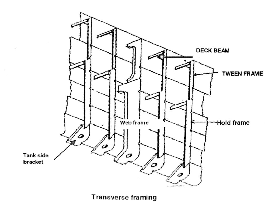
Frames when connected to the transverse be make up the ribs of the ships. Transverse frames run from port to starboard. Where openings in decks are required, they are discontinued and strengthened at these openings to compensate for the loss of strength.
Wooden ships were always built on this system, because closely spaced transverse frames were needed to hold the planks together so that seams could be caulked. It was also necessary to use transverse framing because sailing ships needed considerable transverse strength to enable them to resist the stresses set up by the masts and rigging. The sailing ships with their masts and sails exerted a considerable stress on the hull. This stress tended to distort the transverse shape of the ship.
Longitudinal strength was less important in these ships because they were comparatively small and hogging and sagging stresses were not large.
This system is not the most efficient for steel steamships, but it has continued in general use until recently. This was partly because it was cheap to build and served its purpose and partly because a suitable alternative was not available for many years.
Longitudinal System
With the coming of steamships, racking stresses became less important, but hogging and sagging stresses became more serious as ships grew longer. It soon became obvious that more longitudinal strength could be achieved by running the frames longitudinally (fore and aft), provided that reasonable transverse strength was maintained.
Various attempts were made to do this during the 19th century, but all had serious disadvantages and none were generally adopted. Early in this century, a satisfactory system of longitudinal framing was invented which came to be called the ‘Isherwood System’, after its inventor.
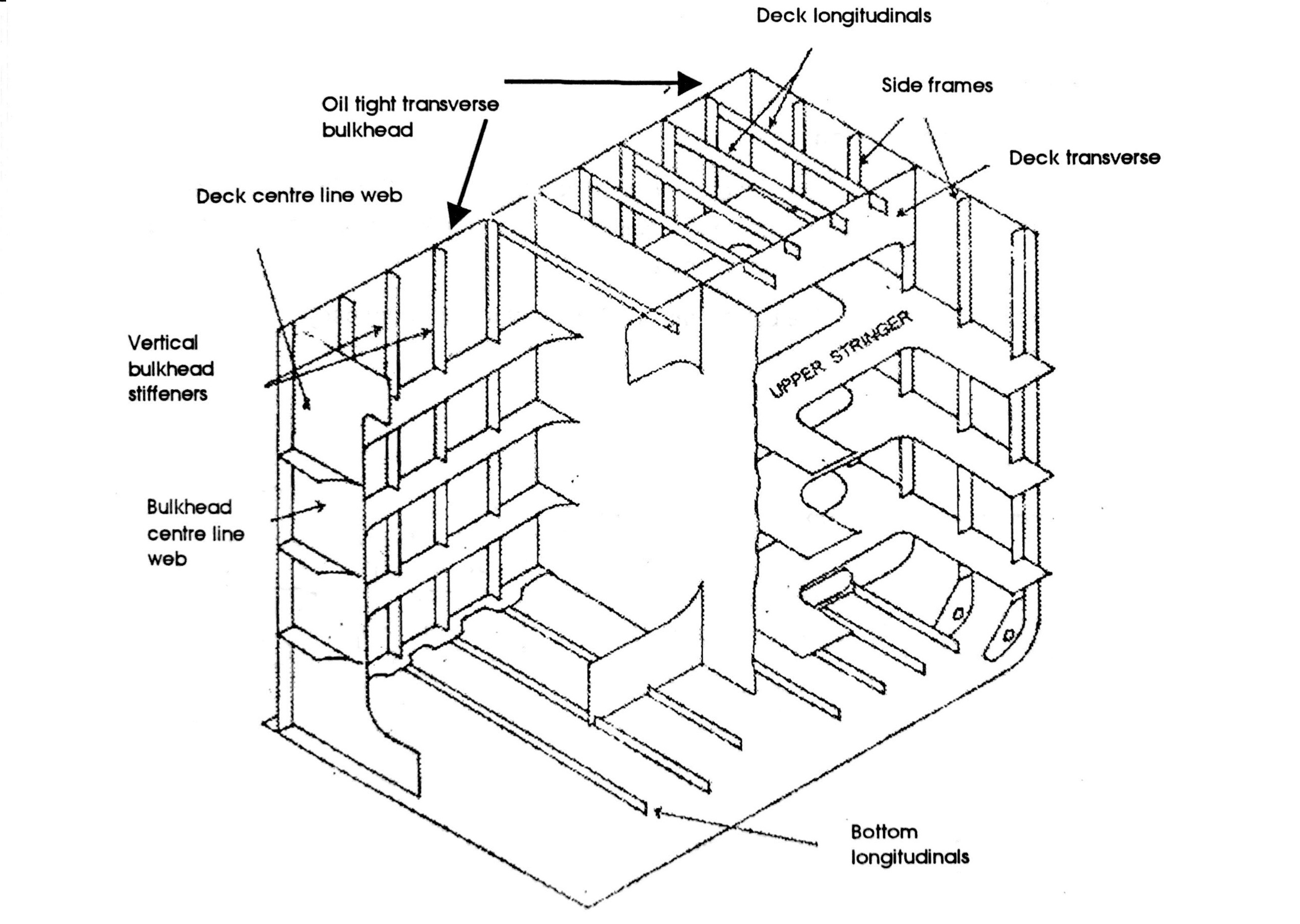
This has longitudinal frames at the bottom, sides and decks, supported by widely spaced transverse web frames, called ‘transverses’. It gave great longitudinal strength and is much used for oil tankers and other types of bulk carrier.
A few dry cargo ships were built on this system, but now it is not used for cargo ships because the transverses interfere too much with the stowage of cargo. A large tanker as shown in the figure serves as a good illustration of the system.
Combination System
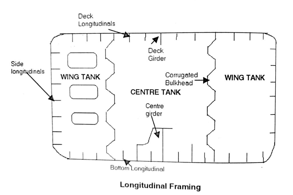
This was introduced to overcome the disadvantages of the longitudinal system for dry cargo ships. The longitudinal frames are retained in the bottom and under the decks where they give great longitudinal strength but transverse frames are fitted on the ship’s side. Where the longitudinal stresses are small, plate floors and heavy transverse beams are fitted at intervals to give transverse strength and to support the longitudinals.
This system was not widely used for riveted ships, although a number were built in this way, but it came more in to use with the coming of all-welded ships. This was partly because it was found that, if these ships were built on the transverse systems, their decks and bottom tended to corrugate under hogging and sagging stresses: whereas the longitudinal frames prevent this. Lloyds’ Rules now require longitudinals to be fitted, in general, in the bottoms and under strength decks of all ships of over 120 metres length.
It seems that this system will eventually replace the transverse framing on all larger dry cargo ships. The combination system is also often used for small to medium-sized oil tankers and for some other types of bulk carriers, for which it has certain advantages.

Cantilever Framing
This is really only a modification of the combination system, but is included here because of its special features. It has been developed for some modern types of ships, which have very long and wide hatchways. These ships do not have enough of decks and beams to give the necessary strength to resist longitudinal and transverse stresses. The strength therefore has to be made up in other ways.
Transverse strength is maintained by using very strong hatch end beams, wherever possible, and by fitting special web frames called ‘cantilevers’ at frequent intervals, abreast of the hatchways.
To give longitudinal strength, the sheer strake and deck stringer plate are much heavier than normal, whilst the hatch side coamings are extra deep and are often made continuous throughout the ship. Sometimes, the hull is also extended upwards at the sheer strake, to form a strong box girder in place of the ordinary bulwark or rails. If the ships are of the ‘twin hatch type’ (with two hatches abreast), a deck girder or longitudinal bulkhead is also fitted at the centre line.
Double bottom
Double bottom is a complex girder placed at the bottom of the ship where the maximum rigidity and strength is required. It is constructed in such a way that the entire double bottom works as one unit. Fig. 4 shows the double bottom tank (DBT) structures in a dry cargo vessel with transverse framing throughout.
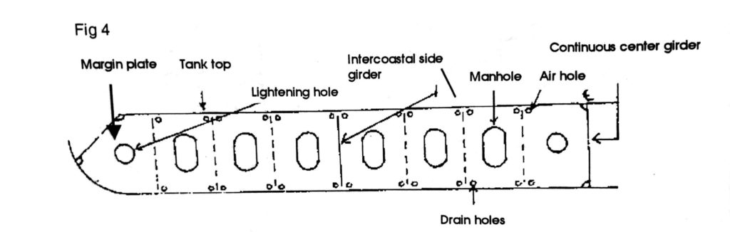
The keel is located at the centre tine forming the backbone and contributes to the longitudinal strength. At the centre of the keel plate and at vertical to it runs the centre girder throughout the length of the keel (except that it gradually terminates forward of the collision bulkhead where the breadth of the V/L decreases drastically and its function is over (purpose is served)). The height of the centre girder determines the depth of the double bottom. This depth may not be constant and may vary to suit the ballast requirements.
Running parallel to the centre girder are one or more side girders (depending on the breadth and the location on the ship. They provide additional strengthening at the base in ore carriers). Bracket floors are in the form of brackets welded on each side of centre girder(s) and to the Margin Plate. (If fitted) In the absence of a margin plate, they extend to the ship’s side.
Solid Plate Floor(s): These are continuous floors extending from shipside/ Margin plate to the centre girder.
The inner & outer bottoms are framed either transversely (usually for V/L less than 120M) or longitudinally (for V/L 120 M or more in length, or if V/L is designed to carry ore or other heavy cargoes).
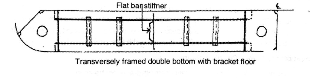
Transversely framed Double Bottoms
There must be a plate floor at every frame space.
► Under the engines
► Under the Deep Tank bulkheads
► Under transverse bulkhead
►Under toes of brackets of deep tank bulkhead
►In the boundary region elsewhere at distances not exceeding 3.05 Metres.
►Bracket floors are placed at every frame space between the plate floors. Vessels of up to 20m in breadth must have one inter-costal side girder on each side. These are to extend as far forward & aft as possible. Additional side girders are provided in the ER and in pounding region. Welded flat bracket floor, which is a vertical welded flat stiffener, is attached to the side girders.
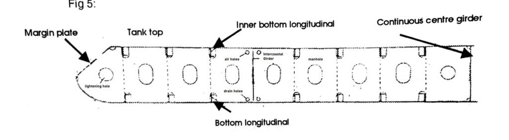
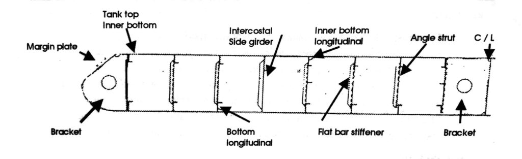
Longitudinally framed Double Bottoms
These double bottoms have plate floors fitted at every frame space. ► Under the engine room plate floors.
► In the region where the vessel tends to pound, that is slamming on the water due to heaving action, particularly in the fore part and ► Under the boiler seats,
► Transverse bulkheads and the toes of stiffener brackets on deep tank.
They are fitted at alternate frames elsewhere.
Solid plate floors provide support to transverse bulkheads and are fitted at intervals not exceeding 3.8 m along the length of the ship. At intermediate frame spaces, brackets are fitted at the tank side & at the centre girders where they may be up to 1.25 m apart. Each bracket is flanged and will extend to the first longitudinal.
One intercostals side girder is fitted on the port and & starboard side, if the ships breadth exceeds 14m, and where it exceeds 21 m, two are fitted on theport & stbd side. Additional side girders are provided as in the case of transversely framed double bottoms. As the unsupported span of the bottom longitudinals should not exceed 2.5m, vertical angle or channel bar struts may be provided to support the longitudinals between widely spaced solid floors.
Deep Tanks
Deep tanks as the name indicates, are tanks, which may extend from one deck to another. Fore peak and the afterpeak tank are the typical examples. They are used to take water ballast, dry cargo or liquid cargo. The tanks are located in the most suitable position for the trade or user requirements.
When they are needed as the ballast tanks they are located near to amidships. If they are used to trim the vessel then the deep tanks will be placed nearer to the ends of the vessel. Deep fore peak and after peak tanks for water ballast serve as trimming tanks in addition to increasing the displacement of the ship when filled.
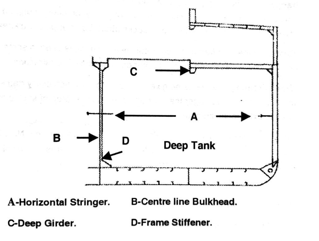
The construction of a deep tank consists of watertight transverse bulkheads at each end of the compartment. The structure of the tank is strengthened to withstand the internal pressure of liquid. Vertical stiffeners are attached to the transverse bulkheads or they may be corrugated for additional strength. Where some special cargoes are carried in such tanks the stiffeners are on the outside of the tank. This provides a smooth surface inside the tank. The deep tank may also rea of the tank. be fitted with a centre line bulkhead to reduce the cross sectional area
Watertight Flats
It is necessary to ensure watertightness when the frame passes through a side stringer plate of a watertight deck. The most common method is to cut the frame at the under side of the watertight flat so that the stringer plate resting on the beams may be fitted close against the shell plating and be connected thereto by means of a continuous fore-and-aft angle bar or weld.
Frames
Welded Frames: –
Flat bars, bulb bars, or inverted angles may be used for these. They may be attached to the hull by intermittent welds, or by continuous fillet welds. They are sometimes scalloped, but this is going out of favour because although it has some advantages, it adds considerably to the difficulties and cost of workmanship if it is to be properly done.
Web Frames: – Are heavy plate frames. These are not normally used but are fitted in certain parts of a ship to give local strength. They must be fitted in engine-rooms and at every fourth frame space in ‘tween decks abaft the after peak bulkhead.
A modification of the web frame, called a ‘cantilever frame’, is used in some types of bulk carrier and is described in the chapter on ‘systems of construction’. ► Deep Framing: – Is the name given to a system in which every frame is made deeper and stronger than normal, over gIven area of shell plating, to provide extra local strength.
Numbering: – Frames are usually numbered from aft to forward, frame No.1 being the first one forward of the sternpost. The frames in cruiser sterns are usually lettered from the sternpost, (aft) forward.
Beams
Transverse beams have two main functions:
►To tie the sides of the ship together and ► To support the deck against water pressure and the weight of cargo. ► Longitudinal beams also contribute to the ship’s longitudinal strength.
Transverse Beams
The size of transverse beams is governed by their unsupported span, the breadth of the ship, and by the load, which the deck has to carry.
Longitudinal Beams
Longitudinal beams or ‘deck longitudinals’ are now required under the strength deck in all ships of over 120 metres long. They are supported at internals by.heavy transverse beams, which must be not more that 2.5 metres apart for the forward 7.5% of the ship’s length. They can be 4.0 metres apart elsewhere. The longitudinals are connected to the transverse beams by direct welding, or by flat bars similar to those used in double bottoms.
At bulkheads, the longitudinals may be cut and bracketed to the bulkhead, as for bottom longitudinals, unless the ship is more than 215 metres long, when the longitudinals must be continuous.
At hatchways, the longitudinals are cut and attached to the hatch end beams by brackets.
Strong Beams
These are often fitted in engine and boiler rooms; to support deck longitudinals, or sometimes, as hatch end beams. In other words, a strong beam is an especially heavy beam, which is fitted, where great local strength is required.
Half-Beams
Transverse beams, which are cut at hatch side coamings, are termed ‘half-beams’. When the coamings do not form part of a deck girder, the half-beams are simply welded directly to it. If the coamings form part of the deck girder, the connection is made by means of alternate flat bars and brackets.
Cargo Suspended from Beams
When cargo is to be suspended from the beams, as in the case of chilled beef, the strength of the beams must be increased by between 50% to 100%, according to circumstances.
Beams may be attached to decks by intermittent or continuous fillet welds, or they may be scalloped, the same way as frames.
Beam Knees are used to connect beams to frames. There are various types, but for connecting frames to ordinary transverse beams the ‘plate bracket knee’ is used almost exclusively.
Welded plate bracket knees are not as efficient as they might be, because they have fairly large stress concentrations at their corners; but they are cheap and easy to fit and are strong enough for purposes where additional strength is not a requirement.
Large knees must have a flange at least 50 millimetres wide on their free edge. Frames and beams do not, in general, overlap, as the knee is considered to be a sufficient connection between them. When longitudinal beams are fitted, the knees at those frames where there is no transverse beam, must extend to the first longitudinal.