The steam generating plant consists of two oil fired auxiliary boilers and one exhaust gas economizer. In port the steam demand of the plant is served by the oil fired boilers. At sea, the steam demand is met by supplying boiler water to the exhaust gas economizer and utilizing the waste heat from the main engine exhaust gas. The steam produced in the exhaust gas economizer is normally sufficient to allow the oil fired boilers to be shut down but at times of high steam demand at sea one of the oil fired auxiliary boilers would be used.
General Construction
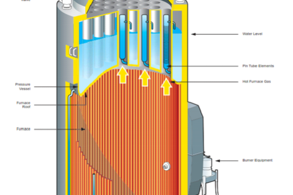
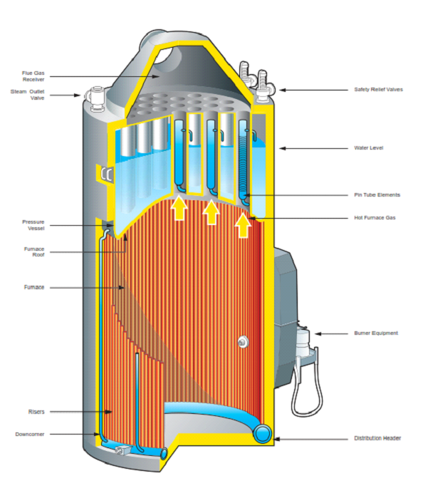
The boiler is of the steel welded vertical cylindrical design, with a combustion chamber and a water/steam drum mounted on top of the combustion chamber. The combustion chamber is lined with fire brick at the bottom and a water wall consisting of down comers and steam generating tubes at the sides. Smoke tubes pass through the water/steam drum to the flue gas box at the top of the boiler. Within each smoke tube there is a finned water tube which extracts heat from the flue gas flowing through the smoke tube.
The boiler is oil fired by a horizontal burner situated in the lower section of the combustion chamber. The burner is of the rotary cup type. Radiant heat from the furnace flame heats the water in the water wall tubes and this promotes water circulation between the water drum and the lower header at the base of the combustion chamber. Steam is generated by the flue gases as they pass through the smoke tubes heating the surrounding water and the water contained in the finned water tubes. The smoke tubes pass through the steam space in the water/steam drum and this provides for drying of the steam.
Manholes and inspection holes are provided for easy access and inspection of the combustion chamber and the steam/water space. A hatch is fitted in the flue gas box for inspection and cleaning.
The boiler is provided with the following mountings:
• Safety valves
• Steam stop valves
• Air vent valve
• Feed water check valves
• Bottom blow down valve and surface blowdown valve
• Pressure gauge
• Reflex water level gauge
• Circulating valves for the economizer
• Heating steam supply valve and condensate drain valve
• Water sampling valve
• Feed regulator float switch
Insulation is provided on the outer surface of the boiler and outermost surface is covered with galvanized steel casing.
Operating Procedure
The following steps should be taken before attempting to flash up the boiler:
a) All foreign materials are to be removed from internal pressure parts.
b) Ensure all gas-side heating surfaces are clean and all refractory is in good condition.
c) The furnace bottom and the burner wind box are to be free from oil and other debris.
d) All manhole doors and inspection covers are to be securely tightened.
e) Inspect safety valves and ensure that gags have been removed and easing levers are in good condition. The safety valve drains must be checked and proved clear.
f) All root valves for instruments and controls connected to the boiler are open.
g) Open the vent valve of the combined water/steam drum.
h) Check and close all blowdown and drain valves.
i) Fill the boiler until the water level appears 25 to 50mm high in the gauge glasses. Allow for swell in the level after firing.
j) Check the operation of the gauge glasses and compare with the remote reading instruments.
Note: Remote reading instruments may not be accurate until steam is being generated.
Manually Raising Pressure with no Steam Available from the Exhaust Gas Boiler
a) Set up the diesel oil systems for the pilot burner and the main burner.
b) Turn the boiler control panel power switch to the ON position. When burning MDO in the main burner, select the oil heater switch to the OFF position and the thermostat bypass switch to the ON position.
c) Purge the furnace with the forced draught fan for a minimum of 40 seconds, preferably one minute with the vanes fully open.
d) Reduce the air pressure at the wind-box to between 12-15kPa
Note: too high a primary air pressure will make ignition difficult and produce an unstable flame. Too low a primary air pressure will result in poor fuel atomization and poor combustion.
e) Set the burner operation switch to the MANU position. The pilot burner will ignite and the furnace will pre-purge for a period of 30 seconds on a timer. After purging the main burner will ignite.
f) Check for stabilized combustion using the furnace observation port and smoke indicator.
g) When raising the pressure, keep the burner firing for 5 minutes and out of service for 15 minutes repeatedly for one hour.
Repeatedly light and shut down the burner to raise pressure as recommended by the manufacturer. A guideline would be to aim for 15kPa after 2.0 hours firing.
h) When the boiler pressure has risen to about 15kPa and all of the air has been displaced out of the vent valve close the steam space vent valve.
i) Drain and warm through all steam supply lines to ancillary equipment before putting the boiler on load.
j) Supply steam to the HFO settling tank. When the HFO settling tank is at a high enough temperature to allow the HFO to be pumped by the auxiliary boiler burner FO pumps, supply steam to the FO heater and prepare to change over from MDO to HFO.
When preparing to burn HFO the oil heater switch is turned to the ON position. Change to HFO burning when operating conditions allow.
k) When the boiler reaches working pressure, switch to automatic operation.
Raising Pressure with Steam Available from the Exhaust Gas Boiler
With the exhaust gas economizer operating one of the oil fired auxiliary boilers acts as a steam and water reservoir with water circulated from the oil fired auxiliary boiler, through the exhaust gas economizer and back to the auxiliary boiler. This boiler will, therefore, be maintained at operating temperature and pressure.
The oil fired auxiliary boilers are fitted with steam heating coils and these are employed to maintain a shutdown boiler in a warm condition when at sea.
Prior to operating an oil fired boiler the HFO must be heated to the correct temperature and the boiler must then be fired in order to raise pressure to the normal operating pressure.
a) Ensure that the HFO setting tank is heated to the desired temperature.
b) Start the forced draught fan, open the inlet vanes and purge the furnace.
c) Start one of the auxiliary boiler burner FO pumps and circulate oil through the heater and burner supply manifold. Open the pressure regulating valve bypass valve so that the cold HFO in the system returns to the pump suction. When the oil is at the desired temperature throttle in the pressure regulating valve bypass valve and open the boiler burner recirculating valve.
d) Reduce the air pressure at the wind box to between 12-15kPa.
e) Close the recirculating valve.
f) Light the main burner and adjust the air supply to ensure an established combustion using the furnace observation port and smoke indicator.
When raising the pressure, keep the burner firing for 5 minutes and out of service for 15 minutes repeatedly for one hour. Repeatedly light and shut down the burner to raise pressure as recommended by the manufacturer. A guideline would be to aim for 1.57MPa after 2.0 hours firing.
g) When the steam pressure has risen to about 0.14MPa and all of the air has been displaced out of the vent cock, close the steam
space vent valve; this should not be necessary if the boiler is maintained under low pressure.
h) When the oil fired auxiliary boiler is at the normal working pressure it may be coupled with the other boiler, or if it is the first boiler to be flashed, it can be used to supply steam to the ship’s systems and the exhaust gas economizer may be shut down.
Shutting Down
a) Change the fuel system to diesel oil before firing is stopped unless a steam supply is to remain available. If steam is
available from the economizer, the boiler HFO system should remain in use.
b) If no steam is to remain available shut down the fuel system when the fuel oil has been fully charged with MDO.
c) Shut down the burner by turning the burner auto switch to the OFF position.
d) Continue the operation of the forced draught fan for a short while after shutting down the burner, keeping an air pressure of 15kPa at the burner inlet. Purge the furnace of combustible gases.
e) Allow the boiler to cool down naturally.
f) Maintain the water level visible at about 50mm in the gauge glass.
g) Open the drum vent valve before the boiler reaches atmospheric pressure.
h) Shut down the boiler at the control panel.
After the boiler has been shut down for 4 hours the forced draught fan may be used to assist cooling down, but to avoid damage to refractory allow the boiler to cool down naturally if possible.
CAUTION : Do not attempt to cool down the boiler by blowing down and then by filling with cold water.
Shutting Down in an Emergency
Should the boiler trip (when the burner is in use) due to the too low water level alarm, with the subsequent trip of the fuel oil supply, shut down the steam stop valve, feed valve and the forced draught fan after purging the furnace.
Note: Never attempt to pump feed water into the boiler until it has cooled sufficiently.
Flame Failure
In the event of flame failure, close the oil inlet valve and reduce the air pressure to prevent over-cooling the furnace.
Purge the furnace before relighting the burner. Always use the pilot burner for ignition.
Note: Never attempt to relight the burner from the hot furnace refractory.
Taking the Boiler Out of Service
When taking a boiler out of service, the wet layup method is preferable, because it requires less preparation and the boiler can be quickly returned to service if necessary.
When the boiler is in the cooling down process following shut down, boiler water, suitably treated with appropriate quantities of boiler chemicals, should be used to fill the boiler. To ensure adequate protection of the boiler, follow the guidelines given by the chemical supplier.
When the pressure is approaching atmospheric pressure, open the steam space air vent valve.
When the pressure is off the boiler, supply chemically treated distilled water until it issues from the vent valve, then close the vent valve.
Put a hydrostatic pressure of 0.25 to 0.4MPa on the boiler. Hold this pressure until the boiler has cooled to ambient temperature. Bleed the boiler using the vent valve to be sure all the air is out. Maintain a hydrostatic pressure of 0.15 – 0.29MPa on the boiler.
Take a periodic boiler water sample and replenish any spent chemicals.
Before returning the boiler to service, drain the boiler to the normal working level and return the chemical content concentration to the normal level by blowing down.
For long lay up periods a dry lay up procedure may be adopted. The boiler internal surfaces are cleaned and the boiler is filled with water containing 200ppm hydrazine. The boiler is then drained and dried before sealing.
Alternatively the boiler water space may be drained and filled with nitrogen before sealing.