
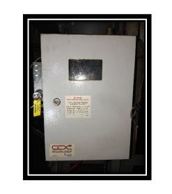
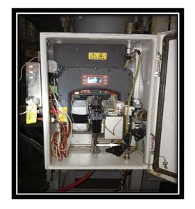
TRO CABINET IN PUMP ROOM
1) Communication Alarm :
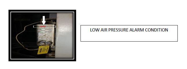
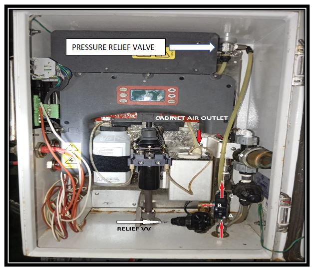
Main cause of communication alarm is low or no air pressure (3 to 4 bar)in the cabinet.
Positive air pressure is to be maintained in TRO cabinet in order to maintain intrinsically safe condition in it.
If the pressure falls below 3Bar the system will stop working and “COMMUNICATION ALARM” will be triggered in the main control panel .
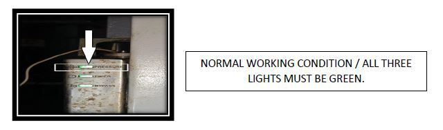
Pressure sensor light provided on the side of cabinet will turn “RED”
TROUBLE SHOOTING FOR COMMUNICATION FAILURE ALARM
1) Check if the supply air pressure is ON.
2) Check the supply air valve to cabinet is OPEN.
3) Increase supply air pressure.
If there the supply air is there and still the pressure Indicator light is RED :-
1) Open the cabinet.
2) Check is there is no leak from the cabinet. Check the packing / sealing of the cabinet.
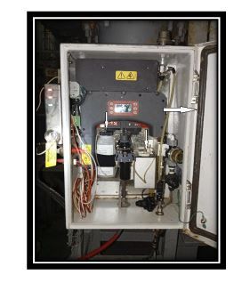
3) Check the air supply control solenoid valve.
a) Check if the solenoid valve is getting electrical signal to OPEN.
b) If signal is there and still there is no air supply in the cabinet , disconnect the solenoid and check if it’s getting charged , if it is getting charged and still there is no air supply then open the valve.
Valve body has one inlet marked as A and two out let marked as B and C on the body.
A is inlet with a strainer , B is connected to pressure relief valve, C is the discharge which is going to “T” connection , one end of the “T” is connected to a second pressure relief valve with over pressure release going outside the cabinet and the second end is connected to a tube with opening kept behind the reagent bottle.
At the inlet there is a strainer (non-removable, inside the body) try to clean it and over haul the valve and make sure the fine holes are not choke.
If valve can’t be cleared and solenoid is not getting charged renew the control valve with a new one.
If there in no spare valve on board then temporarily crack open the air in let connection connected to solenoid valve an “A” and allow the air to bleed out in order to pressurize the cabinet.
The PRESSURE light must turn GREEN and the communication alarm must go.
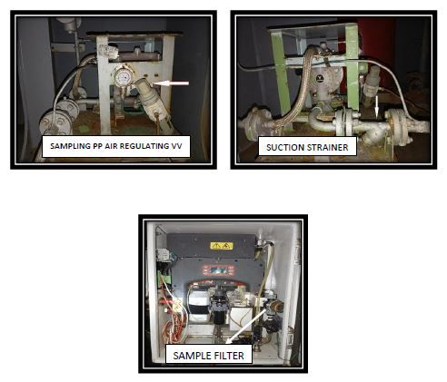
TRO SAMPLING CELL
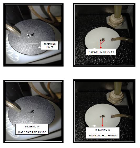
1) Make sure the INDICATOR and BUFFER solution is not expired and prepared as per makers instruction.
2) Make sure the suction tubes are clear and free of air bubbles. Purge the tubes before use.
3) Both the chemical bottles have NON-RETURN BREATHER VALVE ON TOP of them. Make sure that the breathing holes are not clogged and the rubber flaps acting as NRV disks are free to operate.
If the breathing hole are clogged or the flap is stuck the TRO sampling CELL pump won’t be able to take suction properly from the reagent bottles resulting in wrong TRO reading.
Ballast sampling pump
Ballast sampling pump strokes must be adjusted using the flow control valve .Pump should not be run at maximum number of strokes / speed as it will pressurize the sampling line result in undue pressure on the TRO unit . There must be continuous controlled flow through the sampling line.
Sampling pump suction strainer and sample strainer (given inside the TRO cabinet) must be cleaned once a month or if there is a FLOW FAILURE alarm.
Rate of flow must be checked at the ballast water out let going to sample drain tank.
A.F.U
Automatic Back‐flushing Filter Unit
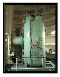
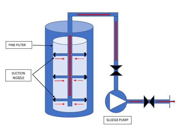
THE back wash filters
Most important part of the AFU is the backwash filter. Back wash filter consists of “SUCTION NOZZLES” , Movement controller unit and sludge pump.
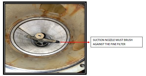
SUCTION NOZZLES :-
Suction nozzles are sacrificial type. There protruding end is spring loaded and it must rub against the metal fine filter. There shouldn’t be any gap between the suction nozzles and the fine filter. Gap will reduce the efficiency of back was filter.
Suction nozzles are plug and play type. Suction nozzles must be inspected at a gap of max 180Hrs of use and must be renewed if required.
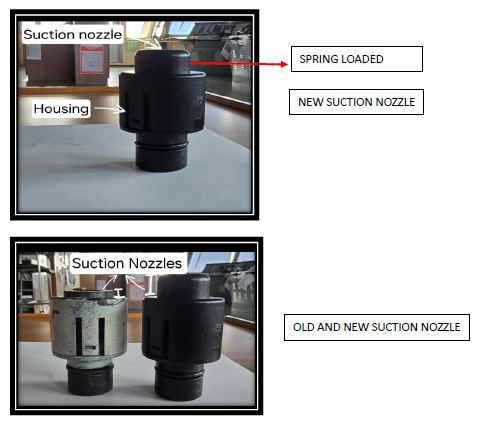
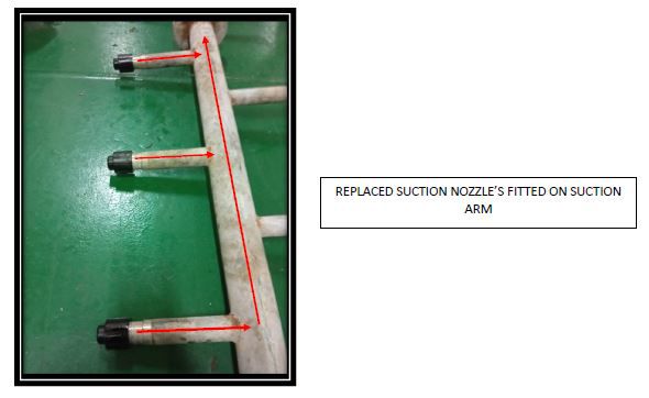
The moment the spring-loaded suction nozzle will get wasted due to abrasion, the body of the nozzle will come in contact with the fine filter and the nozzle will break resulting in bigger orifice opening for suction which in turn will reduce the suction effect drastically and the efficiency of AFU will drop drastically and eventually the fine filter will get clogged within few hours of operation.
BACK FLUSH SUCTION ARM MOVEMENT MECHANISM
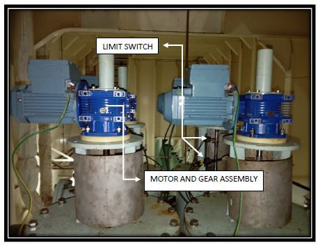
Suction arm of back water flush rotates and moves up and down in order to cover entire surface of fine filter using a motor and gear mechanism.
There are two limit switches on each arm , when these switches get activated the direction of vertical movement of suction arm changes.
This movement much be checked frequently to make sure that the suction arm is rotating freely and the direction of vertical movement is changing once the limit switches are getting activated.
FINE FILTER WILL GET CLOGGED IF THE ARM STOPS ROTATING AND MOVING UP AND DOWN FREELY.
SLUDGE PUMP :
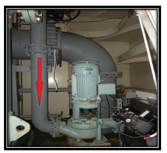
Proper operation and monitoring of sludge pump are as important as operation and monitoring of ballast pump itself.
Many times, this pump rotates in opposite direction as most of the ships have retrofitted BWTS and wiring mistakes is quite common.
Sludge pump takes suction via SUCTION NOZZLES fitted on the suction arm and pumps it over board.
Prior starting BWTS line up of sludge pump must be cross checked. Sludge pump discharge valve is automatic , proper operation of this valve must be cross checked. OPEN / SHUT indicator provided on top of the actuator must be matched with actual position of the spindle to make sure valve is actually opening when the pump starts and closed when sludge pump stops.
Suction and discharge pressure of sludge pump must be monitored frequently to make sure suction pressure is less than discharge pressure , if that’s not the case then following issues can be suspected :
a) Too many broken nozzles.
b) Wrong line up.
c) Discharge valve is not opening properly.
All these issues will result in clogging of AFU fine filter and decrease in ballasting rate.
WATER MOVEMENT IN BACK FLUSH SYSTEM VIA SLUDGE PUMP
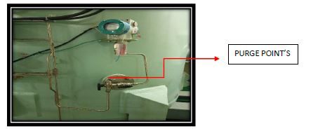
AFTER EVERY BALLASTING OPERATION PUMP OUT THE SALT WATER FROM AFU AND FILL IT WITH FRESH WATER.
AFTER FILLING WITH FRESH WATER OR AFTER DOING MAINTANENCE ON AFU FILTERS ALL THE SENSING TUBES FITTED ON THE AFU MUST BE PURGED USING THE PURGE POINT PROVIDED AT END OF EACH TUBE OTHERWISE WE MAY GET FALSE PRESSURE DIFFERENTIAL READING.
CARE AND MAINTANENCE OF EDU
Electrolytic Disinfection Unit
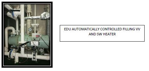
Booster pump feeds SW water to EDU through a small back wash filter fitted in Erm.
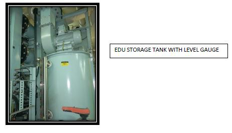
EDU sea water inlet valve is an automatic valve which open’s and close’s as per the level of EDU storage tank.
EDU tank will over flow or get empty if the inlet valve and or the EDU tank level sensor malfunctions. BWTS will trip if the EDU storage tank high level or low alarm gets triggered.
EDU inlet valve must be kept in AUTO mode at all times. There is a clutch provided on this valve to engage and disengage the pneumatic actuator.
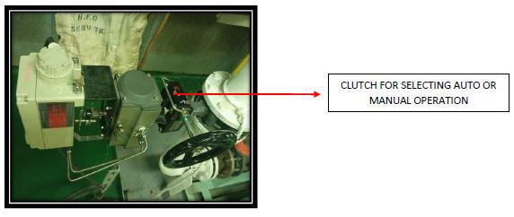
If the pneumatic actuator / valve is not getting operated automatically then manufacturer to be contacted for trouble shooting and till then this valve has to be operated manually to maintain min 60% level in EDU storage tank.
There is a dosing pump which takes suction from EDU storage tank and feeds the oxidant (electrolyzed water / mainly sodium hypochlorite) to ballast being taken.
There is an automatic pneumatically operated dosing valve at the discharge side of the dosing pump. This valve must be kept in AUTO mode at all times by correctly setting the clutch position. Dosing valve opens and closed basis ballasting rate. This valve does not control the EDU storage tank level. Operation of dosing valve effects the TRO reading . If the pneumatic actuator / valve is not getting operated automatically then manufacturer to be contacted for trouble shooting.
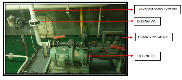
The discharge side of Dosing pump is connected to the discharge side of ballast pump. There are NRV’s provided at the discharge side of dosing pump just before the dosing line enters the pump room. These NRV’S prevents the back flow of water from ballast pump to EDU in case of pressure surge.
EDU storage tank level and Dosing pump flow rate can be monitored in CCR. Suction and discharge pressure gauge are provided near the pump.
A good watch is to be maintained on the EDU storage tank level , dosing pump flow rate and dosing pump discharge pressure to confirm there is continuous flow of electrolyzed water to the ballast pump.
Sufficient number of ballast tank valves must be kept open to avoid pressurizing of dosing line. High back pressure in dosing line may result in improper or no mixing of electrolyzed water during ballast which will affect TRO reading.
As per past experience EDU gives better performance when the feed water temperature is above 30 deg cel. Heater can be used to increase feed water temperature .
EDU to be flushed with fresh water after every use to avoid sediment accumulation on the EDU electrodes. Because of sedimentation EDU will draw more current , the efficiency of electrodes will fall and system my trip due to high current.
ANU UNIT
Automatic Neutralization Unit
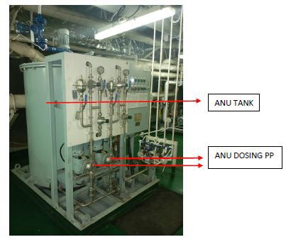
Automatic neutralization unit is used to neutralizing residual chlorite in the treated ballast water during de-ballasting process. Na2S2O3 solution is used as the neutralizer. NaCl and Na2SO4 produced in the neutralization reaction are mild chemicals which will not pose risks to receiving waters.
ANU unit has two metering pumps (diaphragm type) with controllable flow rate. Flow rate must be set as per makers instruction.
ANU tank and metering pump must be flushed with FW after every use. ANU discharge line connects to the ballast pump suction side.
AFTER PEAK BALLASTING AND DE BALLASTING On ships where BWTS ARE RETRO FITTED AND THERE IS DEDICATED BWTS SYSTEM PROVIDED FOR APK
On ships where BWTS are retro fitted the APK is used only for storage of SW required for feeding EDU when vessel operates in a port where water density is less than 1.006.
APK to be charged or ballasted with SW using the booster pump ( the one which feeds EDU) and the water must pass through back wash filter at the discharge side of booster pump.
APK ballast will be used as feed for EDU and finally it will be discharged in ballast tanks while ballasting. APK should not be discharged directly to sea.