Admiralty Coefficient:
- It is necessary to obtain an approximation to the power of a ship without resorting to model experiments.
- Admiralty coefficient method is based on the assumption that for small variations in speed the total resistance may be expressed in the form: Rt α SVn
- Originally this method was used to determine the power supplied by the engine.
- Since types of machinery vary considerably it is now considered that the relation between displacement, speed and shaft power (sp) is of more practical value.
- Most merchant ships may be classed as slow or medium speed and for such vessels the index n may be taken as 2.
- Thus, admiralty coefficient

The admiralty coefficient may be regarded as constant for similar ships at their corresponding speeds.
Fuel Coefficient
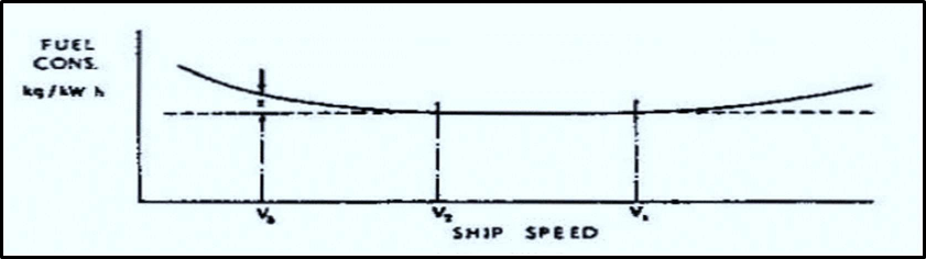
- The fuel consumption of a ship depends upon the power developed; indeed, the overall efficiency of power plant is often measured in terms of the specific fuel consumption which is the consumption per unit of power, expressed in kg/h.
- Efficient diesel engines may have a specific fuel consumption of about 0.20 kg/kW h. while that for a steam turbine may be about 0.30 kg/kW h.
- Between v1 and v2 specific fuel consumption may be regarded as constant
- fuel consumption/day =
(Fuel Coefficient)
- We would keep the Fuel Coefficient and displacement constant for a given ship and compare the fuel consumption at different speed only
Pitch of propeller
- Pitch of a propeller can be defined as the displacement that a propeller makes for every full revolution of 360^\circ. The classification of the propellers on the basis of pitch is as follows.
- The two types of propellers are solid fixed-pitch propeller and controllable pitch propeller.
- The blades in fixed pitch propeller are permanently attached to the hub. The fixed pitch type propellers are casted and the position of the blades and hence the position of the pitch is permanently fixed and cannot be changed during the operation.
- Fixed pitch propellers are robust and reliable as the system doesn’t incorporate any mechanical and hydraulic connection as in Controlled Pitch Propeller (CPP). The manufacturing, installation and operational costs are lower than controlled pitch propeller (CPP) type. The manoeuvrability of fixed pitch propeller is also not as good as CPP.
Percentage apparent slip:
- It refers to the ratio of the actual ship speed to the speed at which the propeller is theoretically designed to operate.
- The percentage apparent is calculated by dividing the actual ship speed by the design pitch speed and multiplying by 100 to express it as a percentage.
- Therefore, apparent slip speed = Vt – V.
- Apparent slip (Percentage apparent) =

Percentage Real Slip:
- Real slip or true slip is the difference between the theoretical speed and the speed of advance expressed as the ratio or percentage of the theoretical speed.
- Real slip speed = Vt – Va in knots.
- Real slip =

Efficiency of Machine:
- The efficiency of a machine refers to the ratio of useful output work or energy to the total input work or energy. In other words, it measures how well a machine converts the input energy into useful output energy. The efficiency of a machine is always expressed as a percentage.
- The efficiency of a machine can be calculated using the following formula:
- Efficiency (%) = (Useful output work or energy / Total input work or energy) × 100%
- In practice, no machine is 100% efficient. Some energy is always lost due to friction, heat, or other inefficiencies within the system. Therefore, the efficiency of a machine is always less than 100%.
- For example, in an ideal scenario, if a machine requires 100 units of energy as input and produces 80 units of useful output energy, the efficiency would be calculated as follows:
- Efficiency (%) = (80 units / 100 units) × 100% = 80%
- In this case, the machine is 80% efficient, meaning 80% of the input energy is converted into useful work, while 20% is lost as waste heat or other forms of energy loss.
Critical Speed of Engine (Bared Speed Range):
- Torque on the flywheel applied by the cylinder is greatest during power stroke and lowest during compression stroke. This varying cyclic torques from each cylinder sets up vibrations in the shafting.
- At a particular speed of engine, this frequency due to vibrations coincides with the natural frequency of shafting system and Resonance is set up. The amplitude of vibration increases till failure of shaft occurs The range of speeds (RPM) of the engine at which the resonant condition occurs is referred to as critical speed range or barred speed range.
- The high stresses due to excessive amplitude of vibrations start to build up, as the RPM approaches this range, and do not come back to some safe value until it passes the barred speed range.
- The unsafe stresses on either side of the critical speed range are referred to as flank stresses.
- Barred speed range of engine can be defined as the range of speeds, from the beginning of build-up of unsafe flank stresses, to the dying away of these stresses at some higher speed.
- Engine should not be operated at this range and it may lead to crank shaft failure.
- This range is usually marked in red colour on the engine tachometers.
Hunting Gear
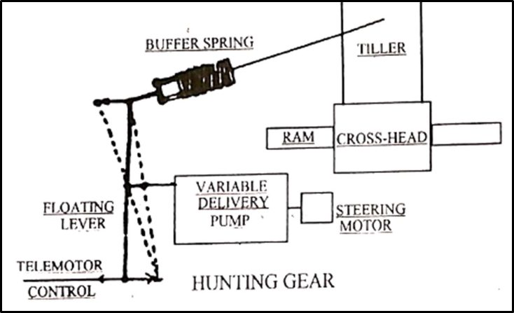
- Initially the steering gear pumps are in a no-delivery state.
- When a rudder movement is received from the bridge telemotor transmitter, the telemotor receiver cylinder will move the floating lever.
- Floating lever will move the floating ring in the variable delivery steering pump.
- This causes a pumping action and moves the tiller.
- The return linkage via buffer spring will cause the floating lever to be re-positioned.
- This re-positioning will cease the pumping when the required rudder angle is reached.
Superheated Steam:
- Superheated steam is a steam whose temperature is higher than the saturated steam at the same pressure.
- Superheater in the boiler receives the saturated steam from steam drum.
- The temperature of this steam is increased by flu gases without increasing the pressure, thus producing superheated steam.
- When steam is superheated, its volume increases approximately in proportion to its increase in absolute temperature.
- Thus, more heat energy is stored in each kilogram.
- This extra energy gives the advantage of using less fuel for the same power and also less likelihood of water hammer in steam piping.
Specific fuel oil consumption and how it is determined
- Specific fuel oil consumption is the measure of mass of fuel consumed per unit time to produce per KW.
- The marine engine efficiency is usually determined using the SFOC.
- Please Note that the fuel consumption and power developed is always measured over a suitable time period on a good weather.
- The readings of flow meter to main engine should be noted over the specified time interval say 1 hour.
- With the difference in flow metre readings before and after this one-hour period, the volume of fuel consumed is obtained.
- Volume when multiplied by density –corrected to the temperature– provides the quantity of fuel consumed.
- Using a dynamometer or the shaft power meter the BHP is calculated, if either of these two are not attached then stick to the old method of getting the value, i.e. Engine RPM, Average Fuel Pump index and with the help of the engine sea trial characteristic curves, get the BHP from the graph.
- But remember, the calorific value of the fuel used at the time of sea trail and what is being used may differ, need to insert the correction factor, else accuracy is a problem.
- SFOC (g/kwh) = Mass of fuel consumed per hour/Power developed in KW
Propeller drop & Rudder drop
Propeller drop:
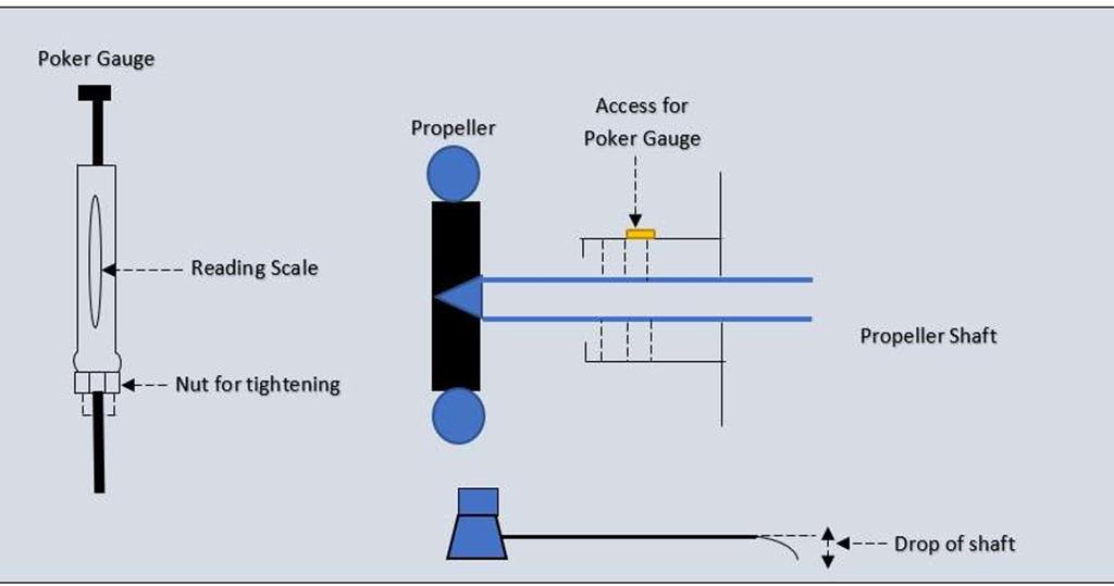
- Forward end of shaft is connected to main engine and at aft end we have propeller fitted on it.
- Basically, it is a cantilever beam with one end fixed and other end free on which propeller is fitted and weight of propeller will try to pull the shaft down.
- A sealing is provided at a point where the propeller shaft passes through the hull into sea to avoid sea water leaking into the engine room.
- This seal contains nitrile rubber or Viton lip seal which seals against the bronze liner shrunk fit around the cast iron propeller shaft.
- Lubrication is provided between liner and sealing to avoid heat build-up and damage the sealing .
- Usually after few years, grooves are created on the liner surface of shaft because of the seals and sealing is lost resulting in sea water leaking in.
- This reduces lubrication effect and creates wear in bronze liner on propeller shaft.
- Now due to the weight of propeller and the clearance developed due to wear, the shaft will come down by a certain amount.
- This drop in propeller shaft is termed as propeller wear down or propeller drop.
- Propeller drop is measured by POKER GUAGE during dry dock.
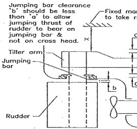
Rudder Drop:
- In heavy weather the rudder may tend to lift up.
- By keeping jumping bar clearance lesser than the clearance at the cross head, the impact force of the rudder when it jumps will be taken by the jumping bar and not by the cross-head.
- Again, with time rudder bearing will keep wearing off due to continuous rudder movements and the clearance will thus keep reducing.
- This clearance is called rudder drop allowance. It is adjusted at the dry dock to a value so that till next dry dock this clearance would have reduced but not sufficiently to cause weight of the rudder to come on the cross head.